


j When using asubwoofer of 70 W (2 Ω), be
sure to connect the subwoofer to the violet
and violet/black leads of this unit. Do not
connect anything to the green and green/
black leads.
k Not used.
l Subwoofer (4 Ω)× 2
Notes
! With a 2 speaker system, do notconnect any-
thing to the speaker leads that are not con-
nected to speakers.
! Change the initial setting of this unit. Refer
to REAR-SP (rear output setting) on page 9.
Refer to PREOUT (preout setting) on page 9.
The subwoofer output of this unit is monau-
ral.
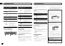
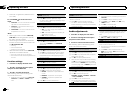
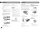
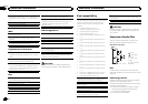
Power amp (sold separately)
Perform these connections when using the op-
tional amplifier.
DEH-3400UB and DEH-34UB
1
1
3
2
4
55
3
2
6
77
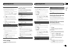
DEH-2400UB and DEH-24UB
1
3
2
6
77
1 System remotecontrol
Connect to Blue/white cable.
2 Power amp (sold separately)
3 Connect withRCA cables (sold separately)
4 ToFront output
5 Front speaker
6 ToRear output or subwoofer output
7 Rearspeaker or subwoofer
Installation
Important
! Check all connections and systems before
final installation.
! Do not use unauthorized parts as this may
cause malfunctions.
! Consult your dealer if installation requires
drilling of holes or other modifications to the
vehicle.
! Do not install this unit where:
— it mayinterfere with operationof the vehicle.
— it maycause injury to a passengeras a result
of a suddenstop.
! The semiconductor laser will be damaged if
it overheats. Install this unit away from hot
places such as near the heater outlet.
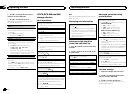
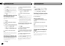
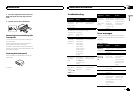
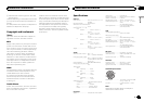
! Optimum performance is obtained when the
unit is installed at an angle of less than 60°.
60°
DIN front/rear mount
This unit can be properly installed using either
front-mount or rear-mount installation.
Use commercially available parts when instal-
ling.
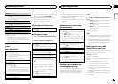
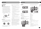
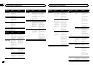
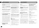
DIN Front-mount
1 Insert the mounting sleeve into the dash-
board.
For installation inshallow spaces, use the sup-
plied mounting sleeve. If there is enough space,
use the mounting sleeve that came with the ve-
hicle.
2 Secure the mounting sleeve byusing a
screwdriver to bend the metal tabs (90°)into
place.
1
2
1 Dashboard
2 Mounting sleeve
3 Install the unit as illustrated.
1
2
3
4
5
1 Nut
2 Firewall or metal support
3 Metal strap
4 Screw
5 Screw (M4 × 8)
# Make sure thatthe unit isinstalled securely in
place. Anunstable installation may causeskipping
or othermalfunctions.
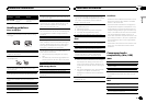
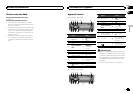
DIN Rear-mount
1 Determine the appropriate position
where the holes on the bracketand the side
of the unit match.
2 Tighten two screws on each side.
1
2
3
1 Screw
2 Mounting bracket
3 Dashboard or console
! Use either truss(5 mm ×8 mm) or flush sur-
face (5 mm× 9 mm)screws, depending on
the bracket screwholes.
Removing the unit
1 Remove the trim ring.
1 Trimring
2 Notched tab
! Releasing thefront panel allows easierac-
cess to thetrim ring.
! When reattachingthe trim ring, pointthe
side withthe notched tab down.
Installation
12
Section
Installation
En
03