


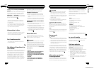
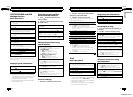
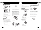
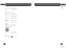

Power amp (sold separately)
Perform these connections when using the
optional amplifier.
1
3
2
4
55
(DEH-3300UB)
1
1
3
2
4
55
3
2
6
77
(DEH-4300UB)
1 System remote control
Connect to Blue/white cable.
2 Power amp (sold separately)
3 Connect with RCA cables (sold separately)
4 To Rear output or subwoofer output
5 Rear speaker or subwoofer
6 To Front output
7 Front speaker
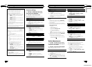
Installation
Important
! Check all connections and systems before
final installation.
! Do not use unauthorized parts as this may
cause malfunctions.
! Consult your dealer if installation requires dril-
ling of holes or other modifications to the vehi-
cle.
! Do not install this unit where:
— it may inter fere with operation of the vehi-
cle.
— it may cause injury to a passenger as a re-
sult of a sudden stop.
! The semiconductor laser will be damaged if it
overheats. Install this unit away from hot
places such as near the heater outlet.
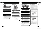
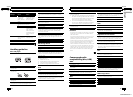
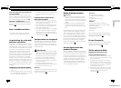
! Optimum performance is obtained when the
unit is installed at an angle of less than 60°.
60°
DIN front/rear mount
This unit can be properly installed using either
front-mount or rear-mount installation.
Use commercially available parts when instal-
ling.
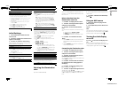
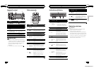
DIN Front-mount
1 Insert the mounting sleeve into the
dashboard.
For installation in shallow spaces, use the sup-
plied mounting sleeve. If there is enough
space, use the mounting sleeve that came
with the vehicle.
2 Secure the mounting sleeve by using a
screwdriver to bend the metal tabs (90°)
into place.
1
2
1 Dashboard
2 Mounting sleeve
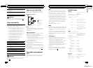
3 Install the unit as illustrated.
1
2
3
4
5
En
16
Section
03
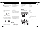
Installation
1 Nut
2 Firewall or metal support
3 Metal strap
4 Screw
5 Screw (M4 × 8)
# Make sure that the unit is installed securely in
place. An unstable installation may cause skip-
ping or other malfunctions.
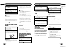
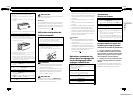
DIN Rear-mount
1 Determine the appropriate position
where the holes on the bracket and the
side of the unit match.
2 Tighten two screws on each side.
1
2
3
1 Screw
2 Mounting bracket
3 Dashboard or console
! Use either truss (5 mm × 8 mm) or flush
sur face (5 mm × 9 mm) screws, depending
on the bracket screw holes.
Removing the unit
1 Remove the trim ring.
1 Trim ring
2 Notched tab
! Releasing the front panel allows easier ac-
cess to the trim ring.
! When reattaching the trim ring, point the
side with the notched tab down.
2 Insert the supplied extraction keys into
both sides of the unit until they click into
place.
3 Pull the unit out of the dashboard.
Removing and re-attaching the
front panel
You can remove the front panel to protect your
unit from theft.
Press the detach button and push the front
panel upward and pull it toward you.
For details, refer to Removing the front panel to
protect your unit from theft and Re-attaching
the front panel on page 5.
Securing the front panel
The front panel can be secured with the sup-
plied screw.
1
1 Screw
En
17
English
Section
03
Installation
<CRD4525-A/N>9