


Connecting the Units
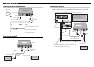
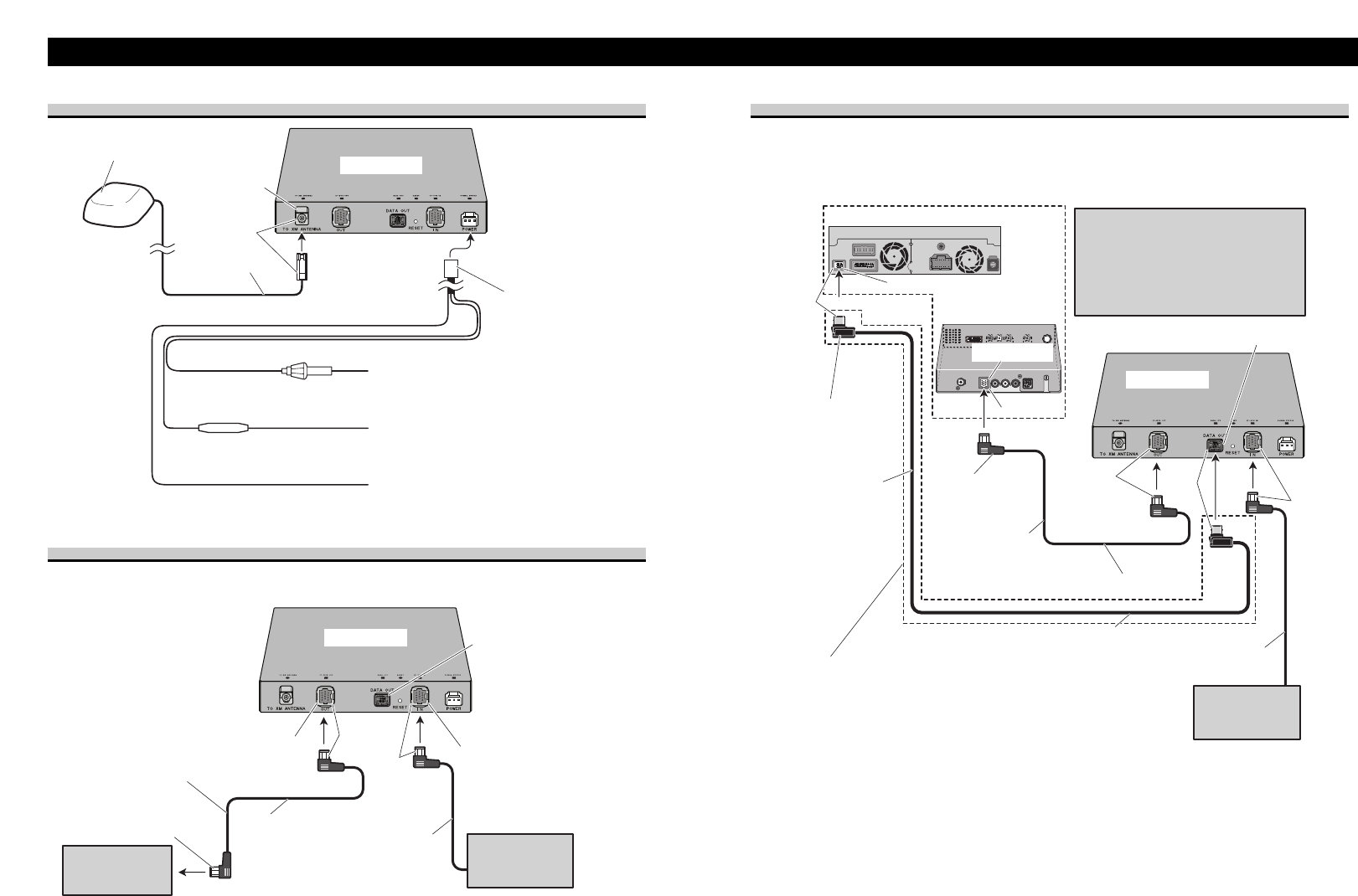
Connecting the power cord and antenna
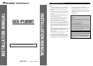
Connecting the system (1)
When using this product with the head unit (or AV head unit) using the IP-BUS only, con-
nect each piece of equipment as below.
This product
Head Unit
(sold separately)
IP-BUS cable
(supplied)
To IP-BUS input (blue)
IP-BUS output
(black)
IP-BUS input
(blue)
Multi-CD player
(sold separately)
IP-BUS cable
Not used.
Black
Blue
3 m (9 ft. 10 in.)
This product
Antenna Input
Power Supply
Antenna Unit
Violet
Yellow
To terminal always supplied with power
regardless of ignition switch position.
Black (ground)
To vehicle (metal) body.
Fuse holder (2 A)
Red
To electric terminal controlled
by ignition switch (12 V DC) ON/OFF.
5m (16 ft. 5 in.)
Fuse resistor
Connecting the system (2)
When connecting this product to the unit, support the data communication functions (e.g.
AVIC-D1, AVIC-N2, AVIC-N1) by both an IP-BUS and XM DATA cable, connect each
equipment as below.
Navigation system (sold separately) (e.g. AVIC-D1, AVIC-N2, AVIC-N1)
Note:
When combining this product with
AVIC-N1 (sold separately), be sure to
updated with the latest map disc
CNDV-50MT [CNDV-50MTP] (sold
separately) to utilize traffic and data
functionality.
Note:
When combining this product with Pioneer navigation system
(sold separately), this connection is required.
IP-BUS Input
DATA OUT port
This product
IP-BUS cable (supplied)
To IP-BUS Input
(Blue)
Multi-CD player
(sold separately)
IP-BUS cable
Black
Blue
3 m (9 ft. 10 in.)
Hide-away unit
EXTENSION port
Display unit
Blue
To EXTENSION
port
3 m (9 ft. 10 in.)
Black
Black
XM DATA cable