


To prevent damage
• Do not ground the speaker wire directly or con-
nect a negative (–) lead wire for several speakers.
• This unit is for vehicles with a 12-volt battery and
negative grounding. Before installing it in a recre-
ational vehicle, truck or bus, check the battery
voltage.
• If the car stereo is kept on for a long time while
the engine is at rest or idling, the battery may go
dead. Turn the car stereo off when the engine is at
rest or idling.
• If the system remote control wire of the amplifier
is connected to the power terminal through the
ignition switch (12 V DC), the amplifier will
always be on when the ignition is on— regardless
of whether the car stereo is on or off. Because of
this, the battery could go dead if the engine is at
rest or idling.
• Speakers to be connected to the amplifier should
conform with the standards listed below. If they
do not conform, they may catch fire, emit smoke
or become damaged. The speaker impedance must
be 2 to 8 ohms for stereo connection, and 4 to 8
ohms for monaural and other bridge connection.
• Install and route the separately sold battery wire
as far away as possible from the speaker wires.
Install and route the separately sold battery wire,
ground wire, speaker wires and the amplifier as
far away as possible from the antenna, antenna
cable and tuner.
• Cords for this product and those for other prod-
ucts may be different colors even if they have the
same function. When connecting this product to
another product, refer to the supplied Installation
manuals of both products and connect cords that
have the same function.
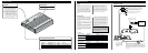
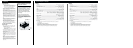
Connection Diagram
Connecting the Unit
CAUTION
• Disconnect the negative (–) terminal of the battery
to avoid the risk of short-circuit and damage to
the unit.
• Secure the wiring with cable clamps or adhesive
tape. To protect the wiring, wrap adhesive tape
around it where they lie against metal parts.
• Do not route wires where they will get hot, for
example where the heater will blow over them. If
the insulation heats up, it may become damaged,
resulting in a short-circuit through the vehicle
body.
• Make sure that wires will not interfere with mov-
ing parts of the vehicle, such as the gearshift,
handbrake or seat sliding mechanism.
• Do not shorten any wires. Otherwise the protec-
tion circuit may fail to work when it should.
• Never feed power to other equipment by cutting
the insulation of the power supply wire to tap
from the wire. The current capacity of the wire
will be exceeded, causing overheating.
Fuse (30 A)
Grommet
Special red battery wire [RD-223] (sold separately)
After making all other connections at the amplifier,
connect the battery wire terminal of the amplifier to
the positive (+) terminal of the battery.
Ground wire (black) [RD-223] (sold separately)
Connect to metal body or chassis.
GM-X962: Fuse (25 A)
× 2
GM-X862: Fuse (25 A) × 2
Car stereo with
RCA output jacks
External Output
Connecting wires with RCA
pin plugs (sold separately).
RCA input jack
Speaker terminal
See the “Connecting the
Speaker wires” section
for speaker connection
instructions.
System remote control wire (sold separately)
Connect the male terminal of this wire to the system remote control
terminal of the car stereo (SYSTEM REMOTE CONTROL). The
female terminal can be connected to the auto-antenna relay control
terminal. If the car stereo does not have a system remote control ter-
minal, connect the male terminal to the power terminal through the
ignition switch.
GM-X962
Speaker Channel Speaker Type Power
Two-channel
Subwoofer Nominal input: Min. 145 W
Other than subwoofer Max. input: Min. 250 W
One-channel
Subwoofer Nominal input: Min. 440 W
Other than subwoofer Max. input: Min. 760 W
GM-X862
Speaker Channel Speaker Type Power
Two-channel
Subwoofer Nominal input: Min. 145 W
Other than subwoofer Max. input: Min. 250 W
One-channel
Subwoofer Nominal input: Min. 440 W
Other than subwoofer Max. input: Min. 760 W
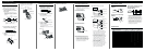
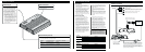
Setting the Unit
Gain Control
If the sound level is too low, even when
the volume of the car stereo used along
with this power amplifier is turned up,
turn gain control on the front of the
power amplifier clockwise. If the sound
distorts when the volume is turned up,
turn the gain control counter-clockwise.
• When using with an RCA equipped car
stereo (standard output of 500 mV), set to
the NORMAL position. When using with
an RCA equipped Pioneer car stereo with
max. output of 4 V or more, adjust level to
match the car stereo output level.
Power Indicator
The power indicator lights when the
power is switched on.
Fuse (30 A)
Front side
Back side
LPF (Low-Pass Filter) Select Switch
Set the LPF select switch as follows according to the type of speaker that is connected to the
speaker output connector and the car stereo system:
LPF Select Audio frequency range Speaker Remarks
Switch to be output Type
LPF (left) Very Low Frequency range Subwoofer Connect a subwoofer.
OFF (right) Full range Full range