


Connecting the Unit
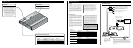
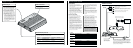
Connecting the Power Terminal
• Always use the special red battery and ground
wire [RD-223], which is sold separately. Connect
the battery wire directly to the car battery positive
terminal (+) and the ground wire to the car body.
1. Pass the battery wire from the
engine compartment to the interior
of the vehicle.
• After making all other connections to the
amplifier, connect the battery wire terminal of
the amplifier to the positive (+) terminal of
the battery.
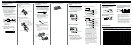
2. Twist the battery wire, ground wire
and system remote control wire.
3. Attach lugs to wire ends. Lugs not
supplied.
• Use pliers, etc., to crimp lugs to wires.
4. Connect the wires to the terminal.
• Fix the wires securely with the terminal
screws.
Fuse (30 A)
Engine
compart-
ment
Interior of
the vehicle
Drill a 14 mm
(1/2 inch) hole
into the vehicle
body.
Insert the O-ring rubber
grommet into the vehicle
body.
Twist
Positive terminal
GND terminal
Power terminal
Battery wire
System remote
control terminal
System remote
control wire
Ground wire
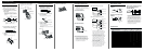
Connecting the Speaker Terminals
1. Expose the end of the speaker wires
using nippers or a cutter by about
10 mm (3/8 inch) and twist.
2. Attach lugs to speaker wire ends.
Lugs not supplied.
• Use pliers, etc., to crimp lugs to wires.
3. Connect the speaker wires to the
speaker terminals.
• Connect the speaker wires, passing them
through the terminal cover.
• Fix the speaker wires securely with the termi-
nal screws.
4. Push on the terminal cover.
10 mm
Twist
Speaker
terminal
Terminal cover
Terminal screw
Speaker wire
Lug
Fuse (30 A)
Battery wire
Ground wire
Lug
Lug
Speaker wire
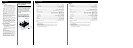
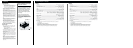
Connecting the Speaker wires
The speaker output mode can be two-chan-
nel (stereo), one-channel (mono), or three-
channel (stereo + mono). Connect the
speaker leads to suit the mode according to
the figures shown below.
Two-channel mode (stereo)
One-channel mode (mono)
Three-channel mode (stereo + mono)
The power amplifier is basically a two-
channel/one-channel bridgeable amplifier,
but three channels can be achieved by
combining the stereo and mono modes
using inductors and capacitors.
Three-channel mode, two-way system
Three-channel mode, three-way system
• Inductors (L1 and L2 in the diagrams)
act as low-pass filters. Capacitors (C1
and C2 in the diagrams) act as high-pass
filters. Inductors (L) are used for the
woofer/subwoofer, and capacitors (C)
are used for the high/mid-high.
• Remember when bridging an amplifier it
will see only half of the original speaker
impedance. Therefore, you must use
speakers that have ratings of 4 ohms or
higher. If you use speakers that have
lower impedance ratings it may cause
damage to the amplifier.
• When the inductors and capacitors are
connected to the speaker wires, secure or
solder them so they cannot be pulled
loose. Tape or use heat shrink on the
joints to prevent short circuits.
C2
C2
L1
L2
L2
C1
C1
C1
C1
L1
(Right)
Speaker
(Left)
Speaker (Mono)
Mid-high (Right)
Woofer (Mono)
Mid-high (Left)
High/mid-high
(Right)
Mid/mid-bass
(Right)
Woofer/subwoofer
(Mono)
Mid/mid-bass
(Left)
High/mid-high
(Left)
Component Guide
Speaker load Impedance 2 Ω 4 Ω 8 Ω
fc (Hz) L (mH) C (µF) L (mH) C (µF) L (mH) C (µF)
50 6.4 1,600 12.70 800.0 25.50 400.0
80 4.0 1,000 8.00 500.0 16.00 250.0
125 2.5 640 5.10 300.0 10.00 160.0
200 1.6 400 3.20 200.0 6.40 100.0
320 1.0 250 2.00 125.0 4.00 62.0
500 0.64 160 1.30 80.0 2.60 40.0
800 0.4 100 0.80 50.0 1.60 25.0
1,250 0.25 64 0.50 30.0 1.00 16.0
2,000 0.16 40 0.30 20.0 0.64 10.0
3,200 0.1 25 0.20 12.5 0.40 6.2
5,000 0.06 16 0.13 8.0 0.26 4.0
8,000 0.04 10 0.08 5.0 0.16 2.5
10,000 0.03 8 0.06 4.0 0.13 2.0
Setting the Filter Constant
Low-pass filter (for subwoofer/woofer):
6 dB/octave
High-pass filter (for mid/mid-high):
6 dB/octave
Band-pass filter (combination of low-pass
filter and high-pass filter for mid-
bass/mid): 6 dB/octave
• A multi-channel system can be set up using a
combination of filters. The inductance (L) and
capacitance (C) will determine the frequency (fc)
that the speaker will reproduce. Refer to the chart
below to determine the components required.
• Use the capacitors specified. Non-polarized capac-
itors rated at over ±25 V should be used for C1
and C2 in the diagram. Because of the voltage
output of the amplifier, it is very important to use
non-polarized capacitors rated at or over 25 V.
This will prevent a safety hazard.
L2
C2
0dB
–6dB
f
CH
2f
CH
f
CL
f
CL
2
0dB
–6dB
f
C
f
f
C
2
C1
0dB
–6dB
f
C
2f
C
f
L1
(3/8 inch)