


3
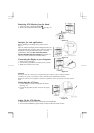
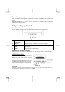
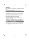
Detaching LCD Monitor from Its Stand
1. Unscrew screws of the hinge bracket
2. Remove the stand from LCD monitor
(See fig. 1-3)
Figure 1-3
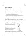
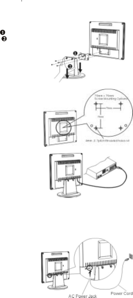
Interface for Arm Applications
Before installing to mounting device, please refer to
Fig.1-3.
The rear of this LCD display has four integrated 4 mm, 0.7
pitches threaded nuts, as well as four 5 mm access holes in
the plastic covering as illustrated in Figure 1-4. These
specifications meet the VESA Flat Panel Monitor
Physical Mounting Interface Standard (paragraphs 2.1
and 2.1.3, version 1, dated 13 November 1997).
Figure 1-4
Connecting the Display to your Computer
1. Power off your computer.
2. Connect the signal cable to the VGA port on your PC.
3. Make sure connection are secure.
Figure 1-5
Attention
This device must be connected to an off-the-shelf video cable in order to comply with FCC
regulations. A ferrite-core interface cable is included in the LCD Monitor package.
This device will not be in compliance with FCC regulations when a non-ferrite-core video cable is
used.
Connecting the AC Power
1. Connect the power cord to the Monitor AC socket.
(See Fig. 1-6)
2. Connect the plug Pin of power cord to an AC power
source.
Figure 1-6
Setting Up the LCD Monitor
1. Make sure the AC power cord is connected to the LCD Monitor.
2. Turn on the LCD Monitor's power switch, located on the bezel of the monitor.