


17
CROSSOVER INSTALLATION
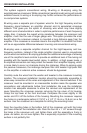
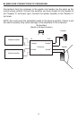
The system supports conventional wiring, Bi-wiring or Bi-amping using the
supplied passive crossovers. While conventional (parallel mode) wiring will provide
excellent sound, bi-wiring or bi-amping may further enhance the performance in
no-compromise systems.
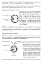
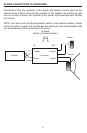
Bi-wiring uses a separate pair of speaker wires for the high frequency and low
frequency signal between an amplifier channel and its associated crossover
network. This gives you the option of choosing wire which may have slightly
different sonic characteristics in order to optimize performance of each frequency
range. Also, it reduces the overall wiring resistance between the crossover and
amplifier, much like the use of larger gauge wire. This option provides the most
benefit when the crossover network is mounted a long distance away from the
amplifier. If the crossover is mounted close to the amplifier it is doubtful that there
will be an appreciable difference between bi-wiring and conventional wiring.
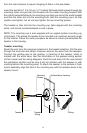
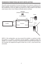
Bi-amping uses a separate amplifier channel for the high-frequency and low-
frequency sections, instead of the single amplifier channel used in conventional
and bi-wired connections. Bi-amping provides the additional advantage of allowing
use of the amplifier's level controls to provide an additional level of fine-tuning not
possible with the tweeter-level switch alone. In addition, at high power levels, a
bi-amplified connection can help protect the tweeter from amplifier clipping, which
is more likely to occur on channels driving the midrange. When bi-amping using
the passive crossovers, the midrange low-pass filter and tweeter high-pass filter
on the amplifier or external active crossover should be bypassed.
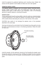
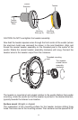
Carefully route the wires from the woofer and tweeter to the crossover mounting
location. The crossover installation location should be reasonably accessible to
allow easy connection of the wires and adjustment of the internal switches. If the
crossover must be mounted in an inaccessible location make the speaker wire
connections and adjustments before final installation. Be sure the installation
location has adequate clearance to allow the removal and replacement of the
cover. Mounting the crossover requires removing the top cover of its housing.
Grasp the top cover at the front and back. Compress the cover slightly in the
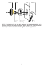
center and lift it off the bottom of the housing. Mounting the crossover requires
four holes in a rectangular pattern 2 13/16" x 4 1/4" (7.14 cm x 10.8 cm) on a flat
surface. Use the crossover as a template for drilling the mounting holes.
Align the mounting holes in the bottom half of the crossover unit with the holes
you have drilled at the installation site. Pass the four #6 x 1 1/4" screws through
the holes in the crossover unit, and tighten them until the assembly is firmly in
place. As before, do not over-tighten; this is especially important if the mounting
surface is not perfectly flat.