


24
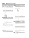
Architect’s and Engineer’s Specification
The Digital Signal Processor (DSP) shall provide two independent
channels of DSP for signal delivery to all professional power
amplifiers. Input and output sensitivity shall be adjustable to
accommodate consumer and pro audio signal levels.
Output Peak Limiter—For each audio channel, the DSP shall
provide a peak limiter that is assignable anywhere in the
signal chain and can be bypassed. Its operation shall be
based upon the peak signal level. The limiter shall provide
the following adjustments:
Gain
Threshold
Attack time
Release time
Predictive Delay
High- and Low-Pass Filters—For each channel of audio, the
DSP will provide high-pass and low-pass filters that are
assignable anywhere in the audio chain. The DSP shall
provide the following crossover responses:
Butterworth (6,12,18,24 dB per octave slope)
Bessel (6,12,18,24 dB per octave slope)
Linkwitz-Riley (12 & 24 dB per octave slope)
High- and Low-Pass Shelf Filters—For each audio channel, the
DSP shall provide high-pass and low-pass shelf filters
that are assignable anywhere in the audio chain. The
shelf filters must be capable of being bypassed. The DSP
shall provide the following shelf filter adjustments:
Variable corner frequency
Variable gain
Variable slope
Contact Closure I/O—The DSP shall provide a trigger input
usable for contact-closure (or other) purpose which shall
be CMOS & TTL signal compatible.
Compressor-- The DSP shall provide a signal compressor that is
assignable anywhere in the signal chain. It shall be based
upon the RMS signal level. The compressor shall be
capable of being bypassed. The compressor shall provide
the following adjustments:
Gain
Threshold
Attack time
Release time
Compression ratio
Predictive Delay
Power Supply—The DSP shall be provided power from an inter-
nal power supply that operates from line voltages in the
range of 100-240 VAC and frequencies from 40 to 63
Hertz. Line cord connection to the DSP shall be via an IEC-
type line cord receptacle.
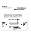
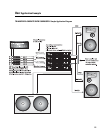
Amplifier Interface—The DSP shall connect to amplifiers using
standard 3-pin XLR connections. Provisions for both bal-
anced and unbalanced connection shall be provided.
Noise & Tone Generation-- The DSP shall provide pink and
white noise generation capability. It shall also provide for
user-specified tone generation. Level control of noise
and tone objects shall be provided
Presets— The DSP shall be capable of storing eight preset
configurations. Preset recall capability shall be via two
front panel push-button switches and shall not require
the use of a computer. The control software shall provide
management of these presets.
General—All audio inputs and outputs shall be balanced. Audio
input and output sensitivity shall be programmable using
the control software. Units will be user-selectable from
dBu, dBV and Volts (rms).
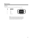
Control— The DSP shall be configurable via a front panel acces-
sible RS-232 port.
The Digital Signal Processor shall be the QSC DSP-30.