


10
EN
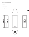
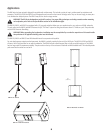
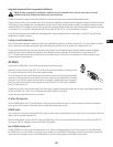
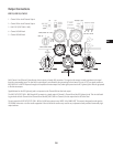
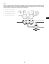
Integrated Suspension Points (suspended installations)
WARNING! When suspending the loudspeakers, installation must be accomplished by or under the supervision of a licensed
installation professional. All applicable building codes must be followed.
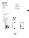
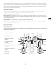
The KW122 enclosure has eight, and the KW152 and KW153 enclosures each feature eleven load-rated M10 installation points.
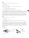
As shipped from the factory, each installation point has a flat head screw installed to acoustically seal the loudspeaker system and retain the sleek look
of the enclosure. These installation points are designed for use with the QSC forged shoulder eyebolts included in the available accessory kit, model
number KW M10 KIT. The installation points may also be used with any forged shoulder eyebolt with an M10 thread provided the length of the thread
is no less than 1.4" (35 mm). When suspending the KW122 horizontally, the KW SUS KIT 122, with pullback bar, is required.
Ensure all pick-point fasteners are installed and correctly tightened in order to maintain enclosure’s rated strength. Contact QSC Technical Services
department for complete information.
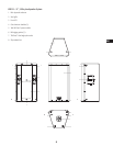
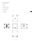
Cooling in Installed Applications
This is a self-powered loudspeaker containing an internal power amplifier that produces heat. Allow a minimum of 6" (152 mm) clearance at cabinet
back for convection cooling. Keep anything that might restrict airflow away from the rear of the enclosure (i.e. draperies, fabric, etc.).
Do not install enclosures with their rear panels exposed to direct sunlight. Direct sunlight will heat the amplifier module and reduce its ability to
produce full output. Install sunshades if the application merits. Maximum ambient temperature for full performance to specification is 50° C
(122° F). Do not install enclosures where exposed to rain or other water sources. The enclosure is not weatherproof. Outdoor installations must
provide protection from the elements.
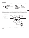
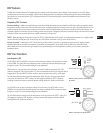
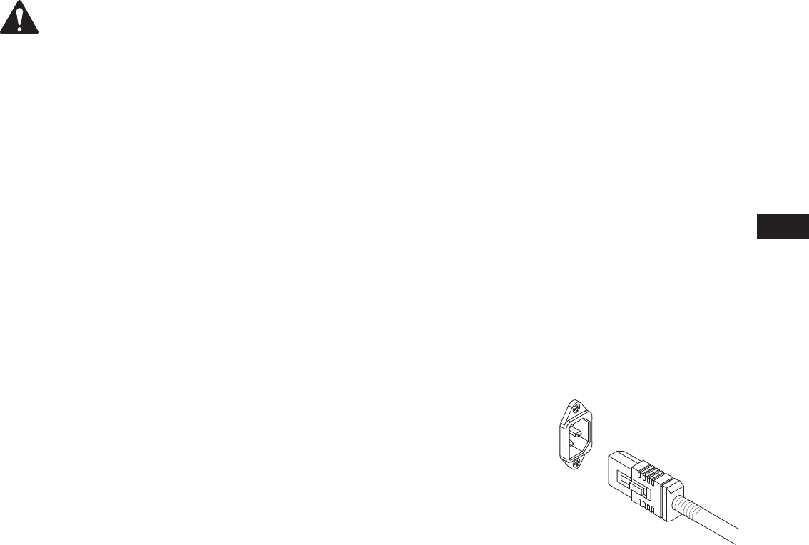
AC Mains
Ensure that the POWER switch is not in the ON position before connecting AC power.
Connect the AC power cord to the AC INLET (IEC) socket on the back of the amplifier by inserting the cord’s
IEC connector fully into the AC INLET on the power amplifier module.
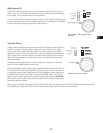
The V-LOCK power cord has a special latching feature to prevent the power cord from being unintentionally
removed. The IEC plug and socket are both blue in color so the power cord can be identified as a KW Series
loudspeaker cord. If the QSC supplied cord becomes lost or damaged, a standard replacement 18 gauge IEC
power cord may be used. However, the latching system functions only with a V-LOCK power cord available
from QSC Audio Products, LLC.
The KW Series is fed by a universal power supply. This power supply is capable of operating the system with AC power input voltages ranging from
100 VAC to 240 VAC at 50 – 60 Hz. There are multiple power cables available for this reason.
Use only the power cable that is correct for your location.
AC Mains Disconnection
Turn the POWER switch to the OFF (not ON) position. Unplug the power cord from the source. To remove the power cord from the loudspeaker
system, grasp the IEC connector’s plastic body, press the yellow latch release button and pull.
POWER Switch
Push in on the top of the rocker switch (labeled ON) to apply AC mains power to the loudspeaker’s power supply. Push in on the bottom of the rocker
switch to turn the powered loudspeaker off.
When in the ON position, the green STBY LED and the red LIMIT (limiter) LED on the rear panel illuminate. After a few seconds the red LIMIT LED
and the green STBY LED extinguish, and the blue POWER LED illuminates.
Rear POWER Indicator LED
The blue POWER LED on the rear panel illuminates when: the AC mains are functioning properly, the AC mains power cord is connected properly,
the POWER switch is in the ON position, and the unit is not in standby. The rear POWER LED extinguishes when the AC mains power cord has been
removed from the loudspeaker or source, the POWER switch is in the off (not ON) position, or the amplifier enters standby.