– 17 –
W
IRING THE
S
YSTEM
NOTICE: If you do not feel comfortable with wiring your new
source unit, please see your local Authorized Rockford Fosgate
Dealer for installation.
• For safety, disconnect the negative lead from the battery prior to
beginning the installation.
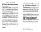
1. Install the 16-Pin Power Harness by connecting the correspond-
ing wires to the electrical and audio system. Solder and heat
shrink all connections for a reliable installation. For each con-
nection, cut a 1" piece of heat shrink tubing and slide over one
of the wires. Strip each wire 3/8" then twist together and solder.
Slide the tubing over the connection and shrink the tubing with
a hot air gun until no bare wire is exposed.
2. Connect the BLACK wire to chassis ground. Prepare the chassis
ground by scraping any paint from the metal surface and thor-
oughly clean the area of all dirt and grease. Strip the end of the
wire and attach a ring connector. Fasten the wire to the chassis
using a non-anodized screw and star washer.
3. Connect the YELLOW wire to a source of constant +12V (for
retaining memory on user-programmed functions). Connect the
Yellow wire to a constant +12 volt positive source. The source
should always have +12V, even when the ignition is off and the
car is not running.
4. Connect the RED wire (Ignition) to a source of switched +12V
(is on only when ignition key is in “accessory” or “run”).
Connect the RED wire to a switched +12 volt positive source.
The switched signal is usually taken from the ACC (accessory)
position of the ignition. If the vehicle does not have an ACC
position, connect the wire to the switched ON position of the
ignition. The current consumption through this wire is negligible.
5. Connect the LT. BLUE wire to the “Remote Turn-On” leads of
the amplifier(s). This will turn-on the external amplifiers when
the source unit is powered on.
6. Connect the BLUE/RED wire to the “Power Antenna” lead. This
will raise a fully automatic antenna when the source unit is
powered on.
– 16 –
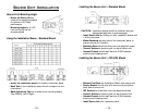
7. Connect the B+, GND and Remote Turn on Wires on the 16 pin
harness according to the Installation Reference Sheet.
8. Connect the AUX* to the external audio source (this inserts the
audio before the volume control on the source unit). The maxi-
mum un-clipped input voltage this circuit can accept is 2.4V
RMS.
Connect the Speaker Wires (if external amplifiers are not used)
to the corresponding speaker leads by soldering and heat shrink-
ing all connections for a reliable installation. If only one pair of
speakers is utilized in the system, use only the FRONT speaker
leads and heat shrink the unused REAR leads to prevent from
shorting out. Be sure to maintain speaker polarity. DO NOT
chassis ground any speaker leads as unstable operation may
result.
9. Install the Preamp Output Harness (if external amplifiers will be
used) by plugging the RCA cables into the corresponding exten-
sion RCAs that feed the input of the amplifiers. Be sure to route
the signal cables away from any high current wires to prevent
coupling noise from radiated electrical fields into the audio sig-
nal.
The FRONT RCAs connect to the Front speaker's amplifier.
The REAR RCAs connect to the Rear speaker's amplifier.
The SUM** RCAs connect to the Subwoofer amplifier.
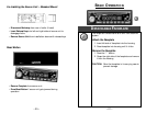
10. Connect the CD Changer (
optional
) by plugging the 8-pin DIN
cable into the connector located at the rear of the source unit.
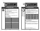
11. Connect the Antenna by plugging the antenna cable into the
connector located at the rear of the source unit. Be sure the
antenna is securely grounded to the vehicle for proper radio
reception.
*Feature available on RFX8230 only
**Feature available on RFX8220 & RFX8230 only


