


6
INSTALLA
TION
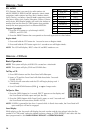
Center Console
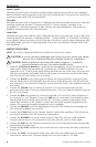
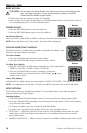
Mounting the source unit in the center console provides optimum access. Be sure the installation
does not interfere with the operation of the gear shift or parking brake. The source unit should have
a mounting angle within ±20° from horizontal.
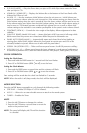
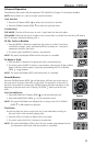
Glove Box
Mounting the source unit in the glove box is adequate, but does not provide easy access. Glove box
mounting should only be done if “Instrument Panel” or ”Center Console,” mounting is not
acceptable (i.e., maintaining integrity of older vehicles with metal dashboards.) The source unit
should be mounted within ±20° from horizontal.
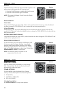
Under Dash
Mounting the source unit under the dash is adequate, but does not provide easy access. Under dash
mounting should only be done if “Instrument Panel,” ”Center Console” or ”Glove Box” mounting is
not acceptable. Mount the source unit off to the side of the driver's area to reduce interference with
the parking brake, gear shift, or operating pedals. The source unit should be mounted within ±20°
from horizontal.
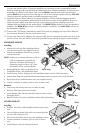
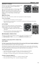
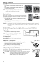
WIRING THE SYSTEM
NOTE: The unit has a diagram decaled to it to help you connect your system.
CAUTION: If you do not feel comfortable with wiring your new source unit, please
see your local Authorized Rockford Fosgate Dealer for installation.
CAUTION: Before installation, disconnect the battery negative (-) terminal to
prevent damage to the unit, fire and/or possible injury.
1. Install the 16-Pin Power Harness by connecting the corresponding wires to the electrical and
audio system. Solder and heat shrink all connections for a reliable installation. For each
connection, cut a 1" piece of heat shrink tubing and slide over one of the wires. Strip each wire
3/8" then twist together and solder. Slide the tubing over the connection and shrink the tubing
with a hot air gun until no bare wire is exposed.
2. Connect the BLACK wire to chassis ground. Prepare the chassis ground by scraping any paint
from the metal surface and thoroughly clean the area of all dirt and grease. Strip the end of the
wire and attach a ring connector. Fasten the wire to the chassis using a non-anodized screw and
star washer.
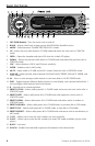
3. Connect the YELLOW wire to a source of constant +12V (for retaining memory on user-
programmed functions). The source should always have +12V, even when the ignition is off and
the car is not running.
4. Connect the RED wire (Ignition) to a source of switched +12V (is on only when ignition key is
in “accessory” or “run” position). Connect the RED wire to a switched +12 volt positive source.
The switched signal is usually taken from the ACC (accessory) position of the ignition. If the
vehicle does not have an ACC position, connect the wire to the switched ON position of the
ignition. The current consumption through this wire is negligible.
5. Connect the ORANGE wire to the lighting switch terminal. This will dim the main display by
30% when the headlights are turned on.
6. Connect the
LT. BLUE wire to the “Remote Turn-On” leads of the amplifier(s). This will turn-on
the external amplifiers when the source unit is powered on.
7. Connect the BLUE/RED wire to the “Power Antenna” lead. This will raise a fully automatic
antenna when the source unit is powered on, but only when the unit is in Tuner Mode.
8. Connect the PINK wire for cell phone mute to the wire on the cell phone harness that provides
ground when the phone rings.
9. Connect the B+, GND and Remote Turn on Wires on the 16 pin harness according to the decal
on the unit.
10. Connect the AUX1* to the external audio source (this inserts the audio before the volume
control on the source unit). The input voltage this circuit can accept is 1–3V RMS.
!
!
* Feature available only on 9210