


EPSON ActionNote 900 Series
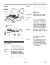
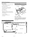
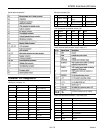
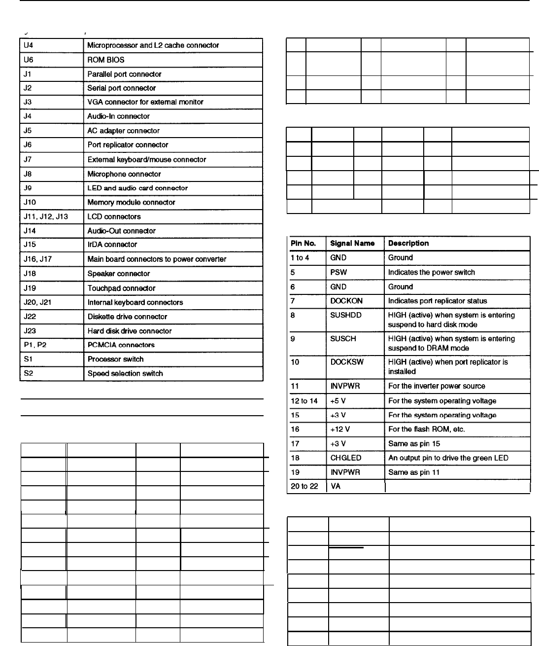
System board components
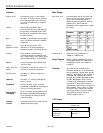
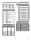
Serial port connector (J2)
Pin Signal
Pin Signal Pin Signal
1
Carder Detect 4
Data Terminal 7
Request to Send
Ready
2
Receive Data 5
Signal Ground 8
Clear to Send
3
Transmit Data 6
Data Set Ready
9
Ring indicator
VGA connectorfor an external monitor (J3)
Pin Signal
Pin Signal Pin
Signal
1
Red
6
Ground
11
NC
2
Green
7
Ground
12
NC
3
Blue
4
NC
8
Ground
13
9 NC
14
Horizontal Sync
Vertical Sync
5
Ground 10
Ground 15 NC
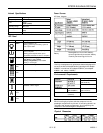
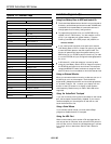
Power converter board connector (22-pin male) (J17’)
Connector Pin Assignments
Parallel port connector (J1)
Pin No.
Signal Name
Pin No.
Signal Name
1
NC 14
AUTO FEED XT
2
Do
15
ERROR
A
constant voltage from AC adapter
3
D1
16
INIT
4
D2
17
SLCT IN
Power converter board connector (14-pin male) (J16)
I I
5
D3
I
18
GND
Pin No.
Signal Name Description
1 to 4
VA
Constant voltage from AC adapter
5
CHGLED
Output pin to drive the orange LED
6
SWITCH
To power on DC/DC converter
6
D4
19
GND
7
D5
20
GND
8
D6
21
GND
9
D7
22
GND
I
7
PWRON
Reserved
8
NC
No connection
10
ACK
23 GND
11
BUSY
24 GND
9 NC
No connection
10
PWROFF
To power off DC/DC converter
11 to 14
GND
Ground
12
PE
13
SLCT
25
PRT SEL
I
10/21/95
AN900-6