


ENFORCER Three- and Four-Channel RF Receiver
2 SECO-LARM U.S.A., Inc.
Each receiver channel can be programmed for one of five different modes, and each individual channel may operate at a
different output mode, depending on the user’s application. The five modes are:
1. Timed Output – Press the transmitter button once. The timed output relay will activate from 1~60 seconds, depending on
the set output time. See page 3 for information on programming the output time. (DEFAULT: 1 second timed output)
2. Toggle Output – Works much like a toggle switch to turn a device ON & OFF alternately. Press the transmitter button
once, and the relay turns ON. Press the transmitter button again, and the relay turns OFF.
3. Latch Output – Press the transmitter button once, and the relay turns ON and stays ON. The relay will remain ON until
the appropriate channel’s transmitter programming button is pressed once to reset, regardless of whether a compatible
transmitter button is pressed again or not.
4. Validity Output – The channel will turn the relay ON for as long as the transmitter button is pressed.
NOTE: Due to possible interference or drops in transmitter battery power while the transmitter button is continuously pressed
(even for short periods of time), the receiver may lose the transmitter’s signal and turn the relay OFF.
1. Press the transmitter programming button of the desired channel to be programmed for 3 seconds or more. The
channel’s LED will start to flash quickly to indicate that it is in the learning mode.
2. While the LED is flashing, press the button of the transmitter to be learned once. The LED will flash once to indicate a
successful learning of that button’s code. After the button has been learned, the receiver will automatically exit the
learning mode. Repeat step 1 to re-enter the learning mode.
NOTE:
The transmitter programming buttons can be found at the rear of the receiver’s case. The button number corresponds
with the channel number. For example, button #1 is the programming button for channel 1.
The channel’s LED will flash for a maximum of 15 seconds. If no transmitter button is pressed during this time, the
receiver will exit the code-learning mode, and the LED will turn off.
If the code being learned has already been learned, the LED for the channel which learned the code will turn steady ON
and then start flashing again. The code will not be learned a second time.
Each channel can learn the codes of a maximum of 15 transmitter buttons. If you attempt to learn a sixteenth transmitter
code, the earliest code will be deleted.
Code Learning a New Transmitter Button:
Each receiver channel can learn the codes of up to 15 different transmitters on a first-in, first-out basis. Below is the
procedure for code learning a new transmitter button. The same procedure applies to each of the receiver’s channels.
Clear Channel Memory:
To clear all codes in the channel’s memory, press the transmitter programming button for that channel for 3 seconds or
more until the LED flashes. Release, and then press that button again for 3 seconds or more until the LED stops flashing.
The LED will then flash twice to indicate that all codes associated with that channel have been deleted.
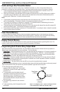
Display Channel Memory:
To see how many codes have been learned in a channel, press that channel’s transmitter programming button once. The
number of codes stored in the channel’s memory is equal to the number of LED flashes.
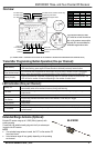
Programming Each Channel Relay Output Mode:
Press the programming mode switch once to
program a channel’s output mode. That channel’s
LED will flash a number of times equal to the output
mode that it is in.
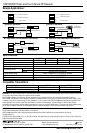
To change modes, press the desired channel’s
mode button. Each press moves to the next mode in
the sequence shown in the diagram to the right.
After changing modes, count the number of times
the channel LED flashes to verify the channel is in
the correct mode.
The programming procedure for each channel is
the same.
To exit programming, press the programming mode
switch again.
NOTE: For a diagram of the PC board, including the location
of the mode buttons, please see Overview, page 3.
Toggle Output
(2 flashes)
Validity Output
(4 flashes)
Timed Output
(1 flash)
Latch Output
(3 flashes)