


ENFORCER Three- and Four-Channel RF Receiver
SECO-LARM U.S.A., Inc. 3
Transmitter Programming Button Operation (One per Channel):
LED Indication (One per Channel):
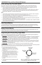
Extended Range Antenna (Optional):
Extends RF receiver range up to 1,000ft (304m) (open air) with
existing remotes.
Comes with a 9ft cable that easily plugs into the 3-pin antenna port
located on the RF receiver.
NOTE:
If an extended range antenna is used, the “LP3” on the receiver PC
board must be cut.
Actual antenna range will vary greatly depending on the operating
environment.
SK-91ERSD
Overview:
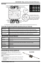
(PC Board shown. Remove the front cover of the receiver to access the mode buttons and terminal block.)
Learn mode
Press and hold the transmitter programming button for three seconds or more.
Clear memory
Press and hold the transmitter programming button for three seconds or more, then when the
LED starts flashing, press again for three seconds to delete all previously learned codes.
Reset latched output
If this channel was programmed for latch output, once the relay is turned ON with a transmitter
button, press the transmitter programming button of that channel once to turn the relay OFF.
Memory display
Press and release the transmitter programming button to show the number of codes stored. The
LED will flash a number of times corresponding to the number of codes stored.
Steady ON
Senses signal from a transmitter button in normal operation, or indicates a transmitter button’s
code already exists in the receiver’s memory during code learning.
Fast flash
In the code-learning mode or channel memory display mode, or during the programming channel
output mode.
One flash
A transmitter button code was learned, or the relay is in timed output mode.
Two flashes
All previously learned transmitter buttons were deleted, or the relay is in toggle
output mode.
Three flashes
Latch output.
Four flashes
Validity output.
0~15 flashes
In the normal operation mode, pressing the channel mode button once will display the number of
codes learned.
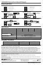
Sec.
SW1
SW2
SW3
1
On
Off
Off
2
Off
On
Off
3
Off
Off
On
4
On
Off
On
5
Off
On
On
10
On
On
Off
30
Off
Off
Off
60
On
On
On
CH 3 Mode switch
CH 2 Mode switch
CH 1 Mode switch
CH 4 Mode switch (4-Channel models only)
Programming mode switch
Time programming DIP switch
Power Input
11~24 VAC/VDC
Channel 1
Channel 2
Channel 3
Channel 4 (4-Channel models only)
Status LED
If an optional antenna is used,
LP3 must be cut and the antenna
slot on the receiver case must be
chipped off to accommodate the
extended range antenna wire.