


– 28 –
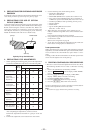
13. ERROR RATE CHECK
13-1. CD Error Rate Check
Checking Procedure :
1. Load the check disc (MD) TDYS-1.
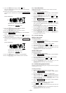
2. Turn the = AMS + knob and display “CPLAY MODE”
(C30).
3. Press the [YES] button twice and display “CPLAY MID”.
4. The display changes to “C1 = AD = ”.
5. Check that the C1 error rate is below 20.
6. Press the [MENU/NO] button, stop playback, press the
[EJECT] button and take out the check disc.
13-2. MO Error Rate Check
Checking Procedure :
1. Load the test disc (MDW-74/AU-1).
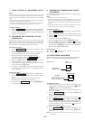
2. Turn the = AMS + knob and display “CPLAY MODE”
(C30).
3. Press the [YES] button and display “CPLAY MID”.
4. The display changes to “C1 = AD = ”.
5. If the C1 error rate is below 50, check that ADER is 00.
6. Press the [MENU/NO] button, stop playback, press the
[EJECT] button and take out the test disc.
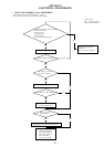
14. FOCUS BIAS CHECK
Change the focus bias and check the focus tolerance amount.
Checking Procedure :
1. Load the continuously-recorded disc. (Refer to “5. CREAT-
ING CONTINUOUSLY-RECORDED DISC”)
2. Turn the = AMS + knob and display “CPLAY MODE”
(C30).
3. Press the
[YES] button twice and display “CPLAY MID”.
4. Press the [MENU/NO] button when “C1 = AD = ” is
displayed.
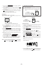
5. Turn the = AMS + knob and display “FBIAS CHECK”
(C05).
6. Press the [YES] button and display “ / c = ”.
The first four digits indicate the C1 error rate, the two digits
after [/] indicate ADER, and the 2 digits after [c =] indicate
the focus bias value.
Check that the C1 error is below 50 and ADER is below 2.
7. Press the [YES] button and display “ / b = ”.
Check that the C1 error is about 200 and ADER is below 2.
8. Press the [YES] button and display “ / a = ”.
Check that the C1 error is about 200 and ADER is below 2
9. Press the [MENU/NO] button, next press the [EJECT] but-
ton and take out the disc.
Note 1: If the C1 error and ADER are above other than the specified
value at points a (step 8. in the above) or b (step 7. in the above),
the focus bias adjustment may not have been carried out prop-
erly. Adjust perform the beginning again.
§
§
§
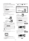
15. AUTO GAIN CONTROL OUTPUT LEVEL
ADJUSTMENT
Be sure to perform this adjustment when the pickup is replaced.
If the adjustment results becomes “Adjust NG!”, the pickup may
be faulty or the servo system circuits may be abnormal.
15-1. CD Auto Gain Control Output Level Adjustment
Adjusting Procedure :
1. Insert the check disc (MD) TDYS-1.
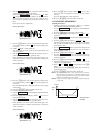
2. Turn the = AMS + knob to display “AG Set (CD)” (C26).
3. When the [YES] button is pressed, the adjustment will be per-
formed automatically.
“Complete!!” will then be displayed momentarily when the
value is recorded in the non-volatile memory, after which the
display changes to “AG Set (CD)”.
4. Press the [EJECT] button and take out the check disc.
15-2. MO Auto Gain Control Output Level Adjustment
Adjusting Procedure :
1. Insert the test disc (MDW-74/AU-1) for recording.
2. Turn the = AMS + knob to display “AG Set (MO)” (C25).
3. When the [YES] button is pressed, the adjustment will be per-
formed automatically.
“Complete!!” will then be displayed momentarily when the
value is recorded in the non-volatile memory, after which the
display changes to “AG Set (MO)”.
4. Press the [EJECT] button and take out the test disc.
§
§