


– 35 – – 36 –
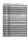
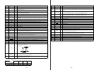
Pin No. Pin Name I/O Description
50 STB O
Relay drive signal output for the power on/off “L”: standby mode, “H”: relay on
51 CHACK IN I
Detection input from the disc chucking-in detect switch “L”: chucking
Not used (fixed at “H”)
52 NC
O Not used (open)
53 PACK-OUT I
Detection input from the loading-out detect switch (S602)
“L” at a load-out position, others: “H”
54 LDIN O
Motor control signal output to the loading motor driver (IC441) “L” active *1
55 LDOUT
O Motor control signal output to the loading motor driver (IC441) “L” active *1
56 LD-LOW
O
Loading motor drive voltage control signal output for the loading motor driver (IC441)
“H” active
57, 58 NC
O Not used (open)
59 REC-P I
Detection input from the recording position detect switch (S601) “L” active
60 PB-P I
Detection input from the playback position detect switch (S604) “L” active
61 REC/PB
O Not used (open)
62 +3.3V
— Power supply terminal (+3.3V)
63
NC O Not used (open)
64 GND
— Ground terminal
65 SDA I/O
Two-way data bus with the EEPROM (IC171)
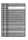
66 MNT3 (SLOCK) I
Spindle servo lock status monitor signal input from the CXD2654R (IC121)
67 WR-PWR
O
Laser power select signal output to the CXD2654R (IC121) and HF module switch circuit
“L”: playback mode, “H”: recording mode
68 PROTECT I
Rec-proof claw detect input from the protect detect switch (S102) “H”: write protect
69 REFLECT I
Detection input from the disc reflection rate detect switch (S102)
“L”: high reflection rate disc, “H”: low reflection rate disc
70 LDON O
Laser diode on/off control signal output to the automatic power control circuit “H”: laser on
71 SENS
I Internal status (SENSE) input from the CXD2654R (IC121)
72 MNT1 (SHOCK) I
Track jump detection signal input from the CXD2654R (IC121)
73 DIG-RST O
Reset signal output to the CXD2654R (IC121) and BH6511FS (IC152) “L”: reset
74 MNT2 (XBUSY) I
Busy signal input from the CXD2654R (IC121)
75 XLATCH
O Serial data latch pulse signal output to the CXD2654R (IC121)
Laser modulation select signal output to the HF module switch circuit
Playback power: “H”, Stop: “L”,
Recording power:
76 MOD
O
77 LIMIT-IN
I
Detection input from the sled limit-in detect switch (S101)
The optical pick-up is inner position when “L”
78
MNT0 (FOK)
I
Focus OK signal input from the CXD2654R (IC121)
“H” is input when focus is on (“L”: NG)
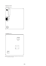
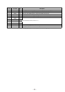
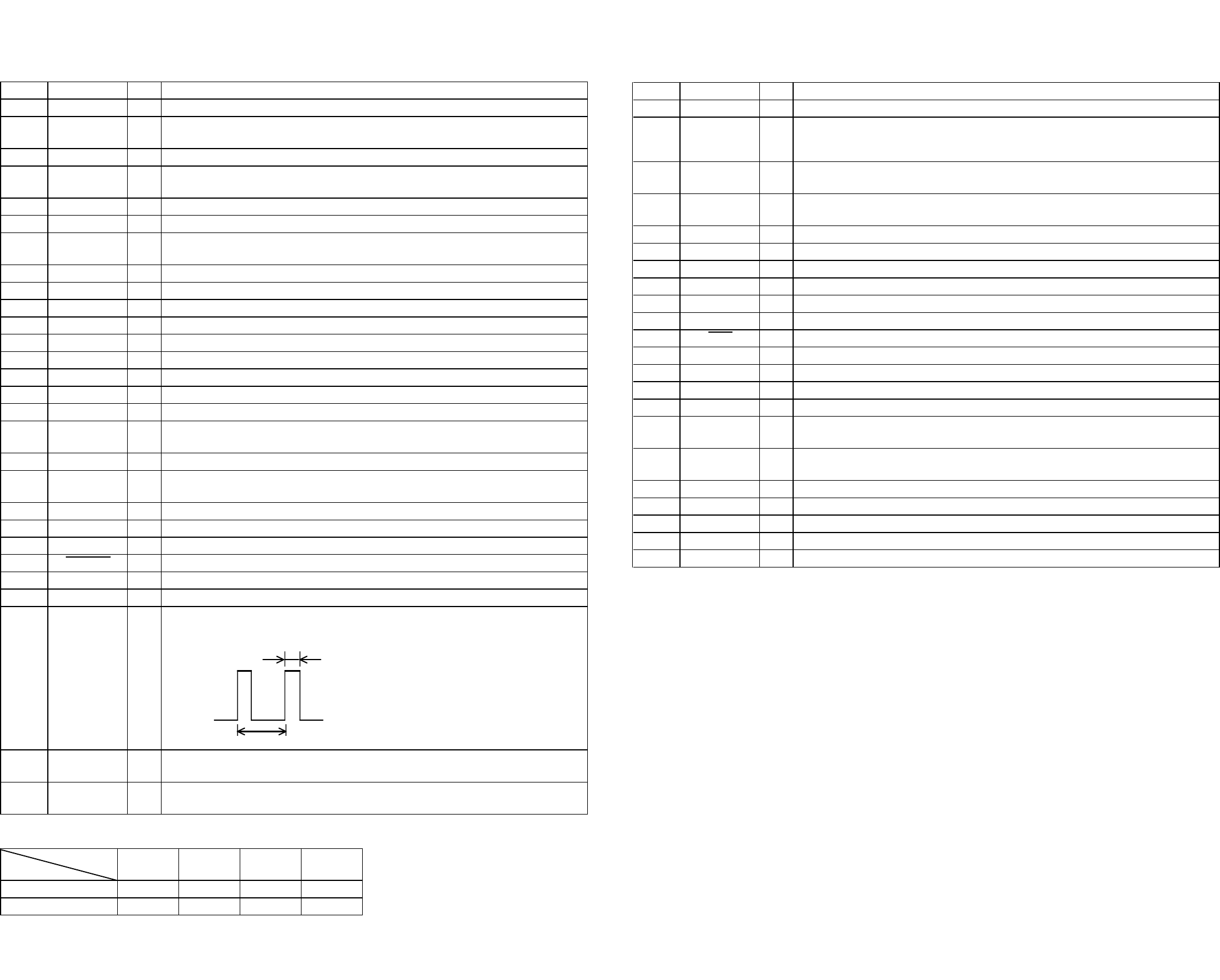
2 sec
0.5 sec
*1 Loading motor (M103) control
LOADING EJECT BRAKE RUN IDLE
LDIN (pin %¢)
“L” “H” “L” “H”
LDOUT (pin %∞)
“H” “L” “L” “H”
Terminal
Mod
e
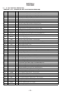
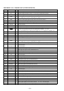
Pin No. Pin Name I/O Description
79 SCL O
Clock signal output to the EEPROM (IC171)
80 SCTX O
Recording data output enable signal output to the CXD2654R (IC121) and overwrite head
driver (IC181) Writing data transmission timing output (Also serves as the magnetic head on/off
output)
81 CLOCK SET0
I
Destination setting terminal
(US and Canadian models: fixed at “L”, AEP, UK and E models: fixed at “H”)
82 CLOCK SET1
I
Destination setting terminal
(US and Canadian models: fixed at “H”, AEP, UK and E models: fixed at “L”)
83
LED0 O
LED drive signal output of the r REC indicator (D741) “L”: LED on
84 LED1 O
LED drive signal output of the · indicator (D742) “L”: LED on
85 OPT SEL0
O Not used (open)
86 OPT SEL1
O Not used (open)
87 MODEL SEL0 I
Setting terminal for the model (fixed at “H” in this set)
88 MODEL SEL1 I
Setting terminal for the model (Not used (open))
89 REC
O Not used (open)
90 BEEP SW
I BEEP switch input terminal “L”: beep off, “H”: beep on Not used
91
NC O Not used (open)
92
SOURCE I INPUT switch (S731) input terminal (A/D input) “L”: digital input, “H”: analog input
93
KEY3 I Key input terminal (A/D input) Not used (fixed at “H”)
94
KEY2 I
Key input terminal (A/D input) S721 to S726 (EJECT §, PLAY MODE, REPEAT, SCROLL,
LEVEL/DISPLAY/CHAR, I/u keys input)
95
KEY1 I
Key input terminal (A/D input)
S711 to S714 (MENU/NO, YES, PUSH ENTER, CLEAR keys input)
96 AVSS
— Ground terminal
97
KEY0 I
Key input terminal (A/D input) S701 to S706 (r REC, p, ), 0, P, · keys input)
98 VREF I Reference voltage (+3.3V) input terminal (for A/D converter)
99 +3.3V
— Power supply terminal (+3.3V) (for analog system )
100
MONO/ST
I
Recording mode switch input terminal “L”: mono, “H”: stereo Not used (open)