


KDL-32EX700/40EX700/40EX703/46EX700/46EX701/46EX703/ 13
52EX700/52EX701/52EX703/60EX700/60EX701/60EX703
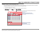
DISASSEMBLY/PART NUMBER INFORMATION
NOTE: Les composants identifi es per un trame et
une marque
!
sont critiques pour la securite.
Ne les remplacer que par une piece portant le
numero specifi e.
NOTE: The components identifi ed by shading
and
!
mark are critical for safety. Replace only
with part number specifi ed.
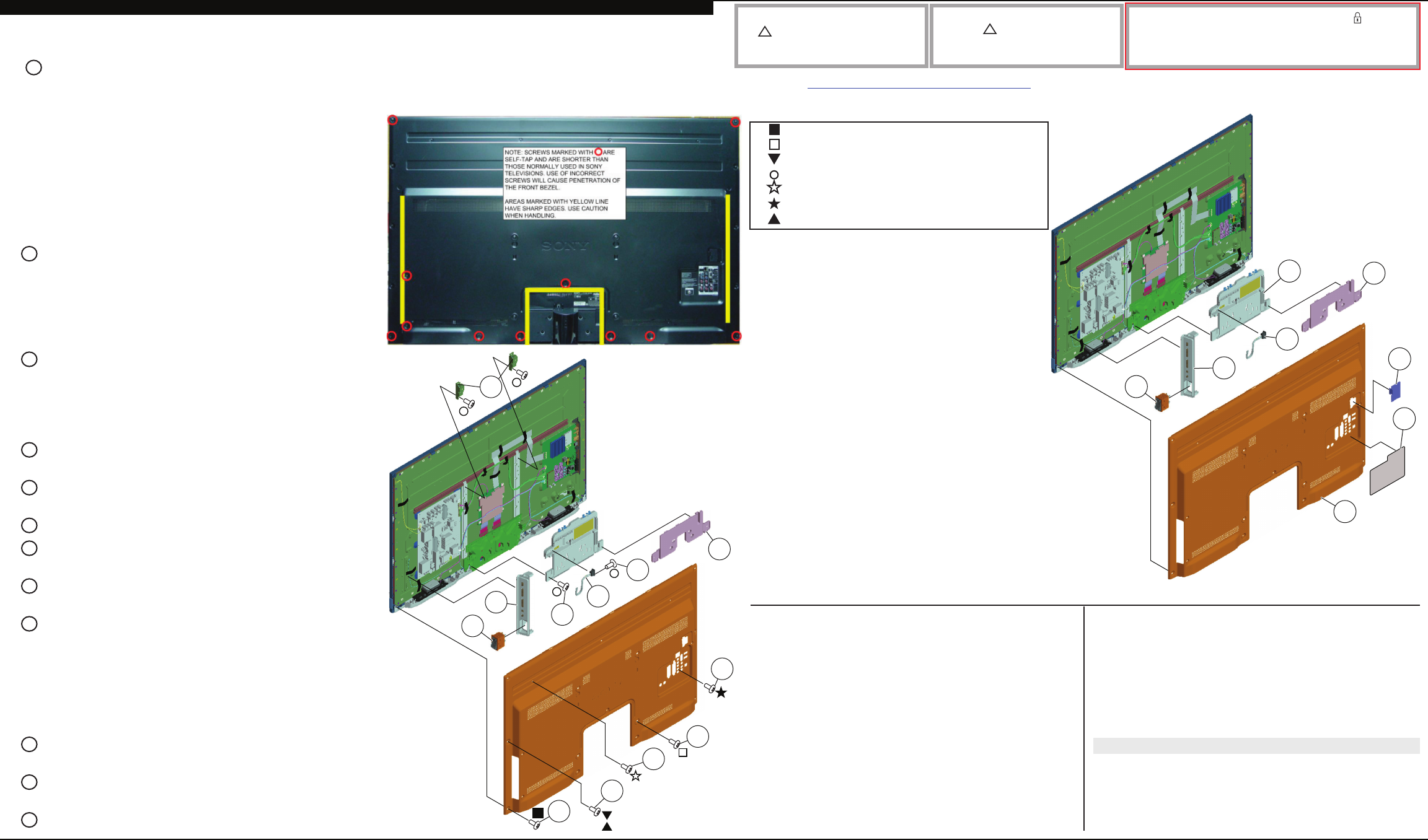
NOTE: The components identifi ed by a red outline and a mark contain
confi dential information. Specifi c instructions must be adhered to whenever
these components are repaired and/or replaced.
See Appendix A: Encryption Key Components in the back of this manual.
REF. NO. PART NO. DESCRIPTION [ASSEMBLY INCLUDES] REF. NO. PART NO. DESCRIPTION [ASSEMBLY INCLUDES]
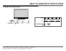
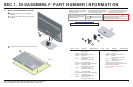
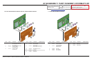
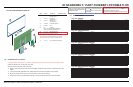
1-2. REAR COVER, SWITCH UNIT, AND POWER SWITCH REMOVAL
A
Remove screws from Rear Cover to detach from Bezel
10 from KDL-32EX700/40EX700/40EX703/46EX700/46EX701/46EX703 Only
12 from KDL-52EX700/52EX701/52EX703/60EX700/60EX701/60EX703 Only
(Check the Sony Electronics Service Information website for any additional service related issues for this model.)
51 X-2541-871-1 REAR COVER(32) ASSY
(KDL-32EX700 ONLY)
51 X-2541-872-1 REAR COVER(40) ASSY
(KDL-40EX700/40EX703 ONLY)
52 4-164-917-01 LABEL, REAR TERMINAL
(US/CND MODELS ONLY)
52 4-164-917-11 LABEL, REAR TERMINAL
(MX MODELS ONLY)
53 3-297-324-02 COVER, ECS
54 4-169-437-01 COVER, HOOK (32)
(KDL-32EX700 ONLY)
54 4-171-125-01 COVER, HOOK (40/46)
(KDL-40EX700/40EX703 ONLY)
55 4-169-434-01 COVER, UNDER (32)
(KDL-32EX700 ONLY)
55 X-2547-768-1 COVER, UNDER (40/46/52) ASSY
(KDL-40EX700/40EX703 ONLY)
! 56 1-842-031-11 AC INLET (2P)
57 1-487-804-11 SWITCH UNIT
58 1-798-309-11 POWER SWITCH
51
52
53
54
55
56
57
58
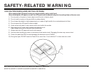
CAUTION: The Rear Covers on the models listed have
sharp edges. Use caution when handling the Rear
Cover to avoid injury. Areas marked with Yellow in
Figure 1 have sharp edges.
The self-tapping screws used to secure the Rear Cover
to the unit are shorter than those normally used on
Sony televisions. Using a longer screw will cause a
penetration of the front bezel assembly.
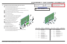
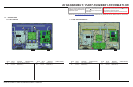
B
Remove screws from Rear Cover to detach from Panel
Bracket
2 from KDL-32EX700/40EX700/40EX703 Only
4 from KDL-46EX700/46EX701/46EX703/52EX700/
52EX701/52EX703 Only
6 from KDL-60EX700/60EX701/60EX703 Only
C
Remove screws from Rear Cover to detach from Panel
3 from KDL-32EX700/40EX700/40EX703/
46EX700/46EX701/46EX703 Only
4 from KDL-52EX700/52EX701/52EX703/
60EX700/60EX701/60EX703 Only
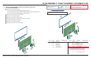
D
Remove 4 screws from Rear Cover to detach from
Vesa Bracket position
E
Remove 1 screw from Rear Cover to detach from
Terminal position
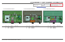
F
Lift Hook Cover to detach from Under Cover
G
Remove 1 screw to detach AC Inlet from Bottom Frame
(KDL-60EX700/60EX701/60EX703 Only)
H
Slide-out AC Inlet to remove from Under Cover
(All Except KDL-60EX700/60EX701/60EX703)
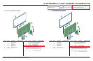
I
Remove screws from Under Cover to detach from
Bottom Frame
2 from KDL-32EX700 Only
5 from KDL-40EX700/40EX703/
46EX700/46EX701/46EX703/
52EX700/52EX701/52EX703 Only
4 from KDL-60EX700/60EX701/60EX703 Only
J
Lift up Switch Unit and disconnect 1 connector to
remove from Panel
K
Slide out Power Switch and disconnect 1 connector to
remove from Switch unit
L
Remove 2 screws to detach Vesa Brackets from Panel
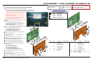
1-2-1. KDL-32EX700 AND KDL-40EX700/40EX703
2-580-639-01 SCREW, +BVTP 4X12 TYPE2 IT-3
2-580-611-01 SCREW, +PSW M6X16
2-580-600-01 SCREW, +PSW M4X8
4-159-298-01 SCREW, +PSW M4X10
2-580-591-01 SCREW, +PSW M3X5
7-685-646-79 SCREW, +BVTP 3X8 TYPE2 IT-3
2-580-603-01 SCREW, +PSW M4X16
A
C
E
F
H
D
J
K
L
B
40/46/52/60
32
I
G