


4
CDX-GT50W/GT500/GT500EE/GT550
TABLE OF CONTENTS
1. GENERAL
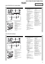
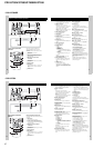
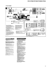
Location of controls and basic operations ............................... 5
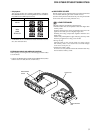
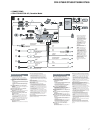
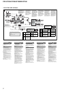
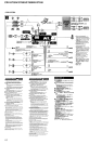
Connections ............................................................................. 7
2. DISASSEMBLY
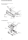
2-1. Sub (FL) Panel Assy ......................................................... 12
2-2. CD Mechanism Block ....................................................... 12
2-3. Main Board ....................................................................... 13
2-4. Chassis (T) Sub Assy ........................................................ 13
2-5. Roller Arm Assy ................................................................ 14
2-6. Chassis (OP) Assy ............................................................. 14
2-7. Optical Pick-up ................................................................. 15
2-8. SL Motor Assy (M902) ..................................................... 15
2-9. LE Motor Assy (M903) ..................................................... 16
2-10. Servo Board....................................................................... 16
3. DIAGRAMS
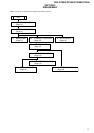
3-1. Block Diagram – CD Section –......................................... 17
3-2. Block Diagram – Main Section –...................................... 18
3-3. Block Diagram – Display Section –.................................. 19
3-4. Circuit Boards Location .................................................... 20
3-5. Printed Wiring Boards – CD Mechanism Section – ......... 21
3-6. Schematic Diagram – CD Mechanism Section (1/2) – ..... 22
3-7. Schematic Diagram – CD Mechanism Section (2/2) – ..... 23
3-8. Printed Wiring Board – Main Section –............................ 24
3-9. Schematic Diagram – Main Section (1/3) –...................... 26
3-10. Schematic Diagram – Main Section (2/3) – ...................... 27
3-11. Schematic Diagram – Main Section (3/3) – ...................... 28
3-12. Printed Wiring Board – Sub Section – .............................. 29
3-13. Schematic Diagram – Sub Section – ................................. 30
3-14. Printed Wiring Board – Key Section –.............................. 31
3-15. Schematic Diagram – Key Section – ................................ 32
4. EXPLODED VIEWS
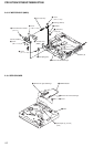
4-1. Main Section ..................................................................... 40
4-2. Front Panel Section ........................................................... 41
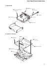
4-3. CD Mechanism Section (1) (MG-611WA-186//Q)........... 42
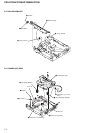
4-4. CD Mechanism Section (2) (MG-611WA-186//Q)........... 43
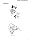
4-5. CD Mechanism Section (3) (MG-611WA-186//Q)........... 44
4-6. CD Mechanism Section (4) (MG-611WA-186//Q)........... 45
5. ELECTRICAL PARTS LIST ........................................ 46