


– 13 –
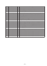
Pin No. Pin Name I/O Pin Description
63 — O Not used.
64 EE CS O Chip select output to EEPROM. (Not used in this set.)
65 EE CKO O Serial clock output to EEPROM. (Not used in this set.)
66 EE SIO I/O Data input from/output to EEPROM. (Not used in this set.)
67 SENS I Internal status input from CXD2652AR (IC200).
68 LIMIT SW I Optical pick-up innermost track limit position detection switch (S400) input
69 DOORSW I Front door open detection switch (S620) input (“L” : Open complete)
70 MD LAT O Serial latch signal output to CXA2523AR (IC100) and CXD2652AR (IC200).
71 MD RST O Reset signal output to CXD2652AR (IC200).
72 VSS — GND
73 MD ON O Servo system power control output (“H” : Power ON)
74 EMPH O O De-emphasis circuit control output (“H” : De-emphasis ON)
75 A ATT I Analog mute control input (“H” : Mute ON)
76 ILLON O Illumination lamp (PL620) light-up control output (“H” : Lamp light-up)
77 TSTSMD I Single mode setting pin (“L” : Single mode)
78 TSTCKO O Serial clock output to LED for TEST mode display. (Not used in this set.)
79 TSTSO O Serial data output to LED for TEST mode display. (Not used in this set.)
80 TSTMOD I TEST mode setting pin (“L” : TEST mode)
81 VDD — Power supply pin (+5 V)
82 – 85 TSTOUT0 – 3 O TEST key output pin of 4 × 8 matrix. (Not used in this set.)
86 – 93 TSTIN0 – 7 I TEST key input pin of 4 × 8 matrix. (Not used in this set.)
94 TEST/VPP — Fixed at “L” in this set.
95 DCS1 I Disc with/without detection 1 switch (S611) input (“H” : with disc)
96 DCS2 I Disc with/without detection 2 switch (S612) input (“H” : with disc)
97 DCS3 I Disc with/without detection 3 switch (S613) input (“H” : with disc)
98 DCS4 I Disc with/without detection 4 switch (S614) input (“H” : with disc)
99 DCS5 I Disc with/without detection 5 switch (S615) input (“H” : with disc)
100 DCS6 I Disc with/without detection 6 switch (S616) input (“H” : with disc)