


– 23 –
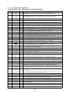
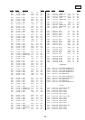
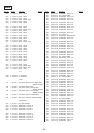
4-9. IC PIN FUNCTION DESCRIPTION
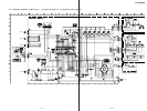
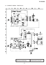
• CONTROL BOARD IC801 TMP87C846N-4D22 (SYSTEM CONTROLLER)
Pin No. Pin Name I/O Description
1 C6DBUP O
Relay drive signal output for the +6 dB gain control (for CENTER input signal)
“H”: +6 dB on
2 C12DBUP O
Relay drive signal output for the +12 dB gain control (for CENTER input signal)
“H”: +12 dB on
3 R6DBUP O
Relay drive signal output for the +6 dB gain control (for REAR input signal) “H”: +6 dB on
4 R12DBUP O
Relay drive signal output for the +12 dB gain control (for REAR input signal) “H”: +12 dB on
5 MAINRY O
Relay drive signal output for the power on/off control “L”: standby mode, “H”: power on
6 OUTDRY O
Relay drive signal output for the INPUT 1 or 2 signal “L”: INPUT 2, “H”: INPUT 1
7 OUTCRY O
Relay drive signal output for the output protect “L”: protect, “H”: releasing of protect
8 OUTBRY O
Relay drive signal output for the BYPASS 2ch input signal “H”: BYPASS 2ch on
9 OUTARY O
Relay drive signal output for the BYPASS 5.1ch input signal “H”: BYPASS 5.1ch on
10 STANDBY LED O
LED drive signal output of the STANDBY LED (D809) “L”: LED on
11 INPUT-1 LED O
LED drive signal output of the input 1 LED (D810) “L”: LED on
12 INPUT-2 LED O
LED drive signal output of the input 2 LED (D811) “L”: LED on
13 BP-5.1CH LED O
LED drive signal output of the BYPASS 5.1ch input LED (D812) “L”: LED on
14 BP-2CH LED O
LED drive signal output of the BYPASS 2ch input LED (D813) “L”: LED on
15 MUTE LED O
LED drive signal output of the MUTING LED (LED on S802) “L”: LED on
16
VOL LED O
LED drive signal output of the master volume LED (D815) “L”: LED on
17
TEST I
Test input terminal (fixed at “L”)
18 RESET I
System reset signal input from the reset signal generator (IC805) “L”: reset
For several hundreds msec. after the power supply rises, “L” is input, then it changes to “H”
19 XIN I
Main system clock input terminal (8 MHz)
20 XOUT O
Main system clock output terminal (8 MHz)
21 VSS —
Ground terminal
22 VAREF I
Reference voltage (+5V) input terminal
23 SW4 I
INPUT SELECTOR switch (S801) input terminal “H”: input 1
24 SW3 I
INPUT SELECTOR switch (S801) input terminal “H”: input 2
25 SW2 I
INPUT SELECTOR switch (S801) input terminal “H”: BYPASS 5.1ch input
26 SW1 I
INPUT SELECTOR switch (S801) input terminal “H”: BYPASS 2ch input
27 MUTE I
MUTING switch (S802) input terminal “L” is input when key pressing
28 W. GAIN I
WOOFER LEVEL up switch (S805) input terminal “L” is input when key pressing
29 R. GAIN I
REAR L/R LEVEL up switch (S804) input terminal “L” is input when key pressing
30 C. GAIN I
CENTER LEVEL up switch (S803) input terminal “L” is input when key pressing
31 W12DBUP O
Relay drive signal output for the +12 dB gain control (for WOOFER input signal)
“H”: +12 dB on
32 W6DBUP O
Relay drive signal output for the +6 dB gain control (for WOOFER input signal)
“H”: +6 dB on
33 A-1 IN I
Sircs remote control signal input for the S-LINK control A1
34 A-1 OUT O
Sircs remote control signal output for the S-LINK control A1
35 — I
Not used (fixed at “L”)
36 SIRCS I
Remote control signal input from the remote control receiver (IC804)
37 VOL+ O Motor drive signal output to the volume motor drive (IC803) (volume up direction)
38 VOL– O Motor drive signal output to the volume motor drive (IC803) (volume down direction)
39 STOP IN I
Trigger input terminal
40 RCL O
Serial clock signal output to the EEPROM (IC802)
41 RDT I/O
Two-way data bus with the EEPROM (IC802)
42 VDD —
Power supply terminal (+5V)