


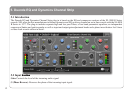
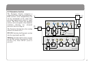

Compressor/Limiter – Introduction
The Channel Compressor/Limiter Section has a number of
key features including a variable compression ratio from 1:1
to
∞
:1, a variable threshold from –20dB to +10dB, auto
sensing attack time (or selectable 1ms attack time), and a
variable release from 0.1 to 4 seconds.
The Compressor/Limiter has two modes of signal detection,
Peak and RMS. As their names suggest these modes of
detection either act on peaks of the incoming signals or on
their RMS or average levels. This gives two very different
modes of compression and limiting with Peak Mode giving
far more dramatic compression characteristics.
Detailed Parameter Description
RATIO: When turned to 1:1, the Compressor/Limiter section
is inactive. Turning the control clockwise increases the
compression ratio to give a true limiter at the fully clockwise
position. The compressor normally has an ‘over-easy’
characteristic. Selecting PK changes this to peak sensing, and
replaces the ‘over–easy’ characteristic with a hard knee,
providing an alternative for some instruments.
THRESHOLD: Whenever a signal exceeds the level set by
this control, the compressor will start to act at the ratio set by
the RATIO control. This control also provides automatic
\make-up gain, so as you lower the threshold and introduce
more compression, the output level is increased, maintaining
a steady output level regardless of the amount of compression.
RELEASE: Sets the time constant (speed) with which the
compressor returns to normal gain settings once the signal has
passed its maximum.
FAST ATT: Provides a fast attack time (3mS for 20dB gain
reduction). When off the attack time is program dependent
(3mS – 30mS).
The yellow and red LEDs, on the bottom of the LED display
area, indicate the amount of gain reduction (compression).
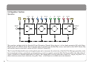
Expander/Gate – Introduction
The gate/expander section contains a number of useful
features including a variable range from 0 to 40dB, a variable
threshold from -30dB to +10dB, a fixed attack time
(switchable to Fast Attack of 100µs), a variable hold time from
0 to four seconds and a variable release time from 0.1 to 4
seconds.
The sidechain signal is sourced from the signal feeding the
dynamics section and the filters and/or equaliser can be
inserted in this sidechain. The green LEDs indicate the amount
of gain reduction on the expander/gate.
By default, the Gate/Expander section functions as an
∞
:1
gate. When the EXP button is pressed, the section becomes a
2:1 expander.
18