


Page 10
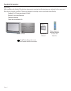
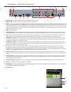
TV Installation – Rear Panel Connections
1
3 4
2
6 7
8
9 10
11
12
95
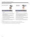
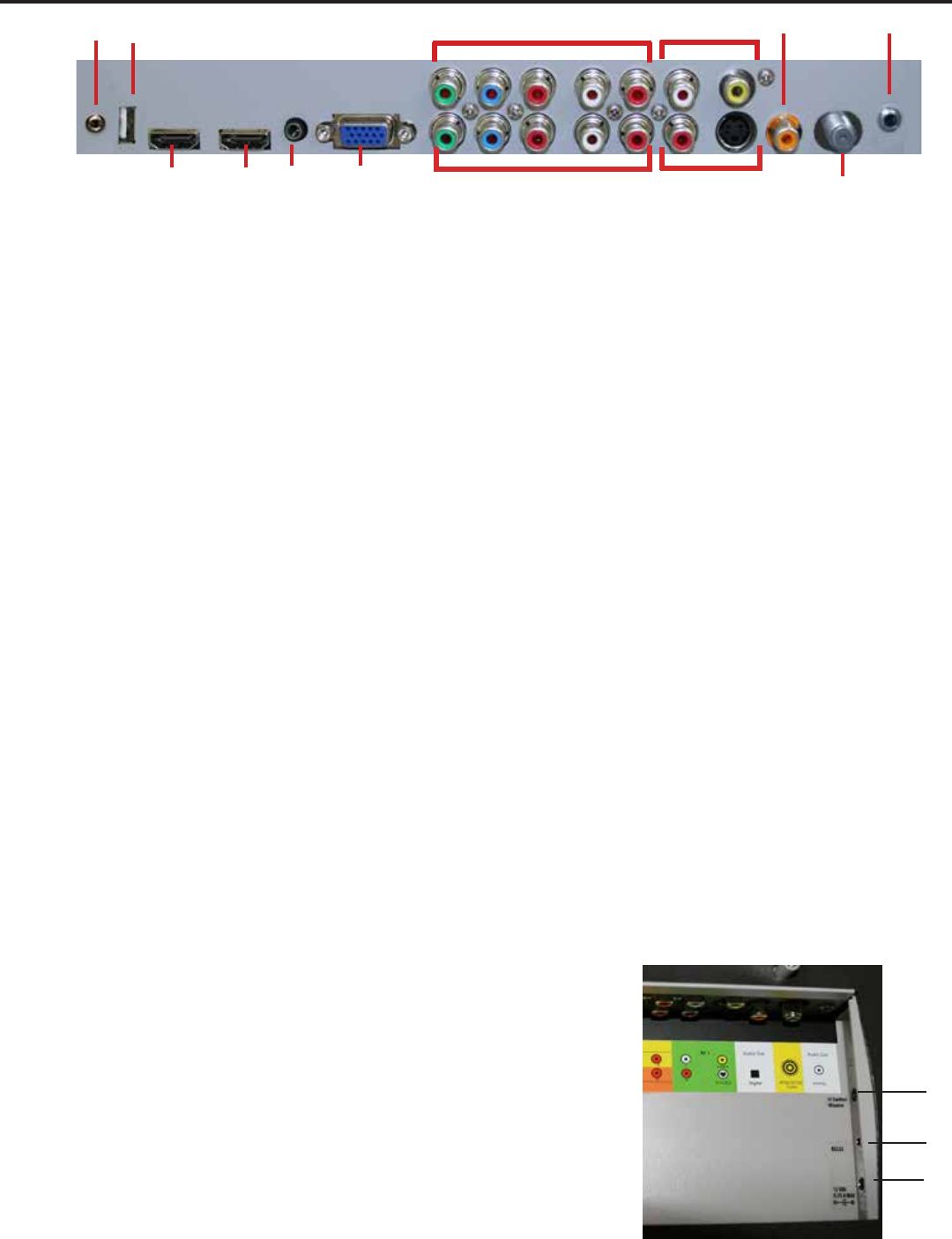
1. SERVICE PORT - This USB Service Port is for factory service only...do not use.
2. SERVICE PORT - This Service Port is for factory service only...do not use.
3. HDMI 1 - Connects to devices that use HDMI cables such as Blu-ray or HD DVD player or HD cable / satellite set-top box. This connection port
receives pure digital audio and high denition signal through one single cable. This port also can accept a HDCP video device for video or PC
for monitor display usage. Use the SOURCE button to select HDMI1 on your MAIN SOURCE to view this connection. Please note: when using
HDMI, your sound signal must be PCM for the TV to decode digital audio. When using this source for PC display, you must connect the audio
cable to VGA Stereo Input for audio.
4. HDMI 2 - Same as HDMI 1
5. VGA STEREO INPUT - This connection port is for people who want to provide audio to the TV when using a PC or a DVI video device. Use a
3.5mm mini-jack audio cable (headphone jack) to provide audio for a HDCP enabled DVI video device or PCs with VGA or DVI connection.
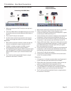
6. VGA - This connection port connects to a PC for video using VGA cable. Be sure to connect your audio cable to the VGA Stereo input if you
want sound out of the VGA video source. Use the SOURCE button to select VGA on your MAIN SOURCE to view this connection.
7. COMPONENT 1 (Lower) - This connection ports are for DVD players or satellite/cable set-top boxes that use component cables. From left
to right, connect green, blue and red for video, and then connect white for left channel audio, red for right channel audio. Use the Source
Button to select YPbPr1 to review this connection.
8. COMPONENT 2 (Upper) - his connection ports are for DVD players or satellite/cable set-top boxes that use component cables. From left
to right, connect green, blue and red for video, and then connect white for left channel audio, red for right channel audio. Use the Source
Button to select YPbPr2 to review this connection.
9. AV 1 (CVBS or S-Video) - Connects to devices that use composite or s-video cables such as VCR or camcorder or video game consoles.
Connect the video portion with either the yellow connector or the S-Video connector. Do NOT connect both video connectors. Use the
SOURCE button to select AV1 (CVBS) on your MAIN SOURCE if you are using the yellow plug for video, use the SOURCE button to select AV1
(S-Video on your MAIN SOURCE if you are using the S-Video connector to view this connection.
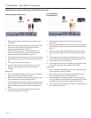
10. DIGITAL AUDIO OUT - This connection port is used for sending out audio signals to other audio devices such as stereo/surround sound
receivers. The orange (SPDIF OUT) connector sends out either bit-stream or PCM digital sound signal to a home theater receiver with digital
input.
11. ATSC/NTSC/QAM – This connection is for digital or analog cable without the cable box or over-the-airwave antennas. The tuner is a hybrid
tuner that tunes to both analog and digital channels. This connection uses coaxial RF cable. For over- the airwave digital stations please
check http://www.antennaweb.org.
12. ANALOG AUDIO OUT (Variable) - Used to connect headphones, stereo receivers and amplied speakers via a 3.5mm headphone jack.
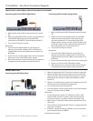
13. RS232 - For remote control using RS232 commands.
14. IR WINDOW - The Internal Infrared (IR) Control Window allows the TV to be controlled from a remote system using IR commands.
(See installation instructions on page 18)
15. 12-VOLT OUT
13
14
15