


Using The TPA311 EVM With the Plug-N-Play Evaluation Platform
3-9
Details
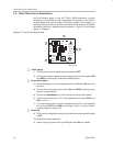
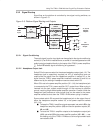
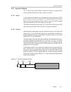
3.3.3.2 Mute/Mode Select (JP6)
A 3-pin jumper header (JP6) on the platform, functioning as a SPDT switch,
routes the control signal from the headphone jack to either the mute control
input pin or the mode control input pin of the evaluation module.
To mute the TPA311 amplifier module using the control signal from the
platform headphone jack, jumper JP6 to
MUTE
To switch the output mode of the TPA311 amplifier between BTL and
single-ended using the control signal from the platform headphone
jack, jumper JP6 to
MODE
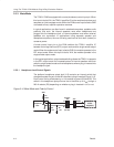
3.3.3.3 Mute/Mode Polarity Select (JP8)
A second 3-pin jumper header (JP8) on the platform selects the control signal
polarity by connecting either the active-high or the active-low line from the
headphone jack to jumper JP6.
When JP6 is set to Mute, use the following JP8 settings for the TPA311:
To mute the TPA311 amplifier module
when
a plug is inserted into the
headphone jack, jumper JP8 to
Hi
(this is the typical setting).
To mute the TPA311 amplifier module
until
a plug is inserted into the
headphone jack, jumper JP8 to
Lo
.
When JP6 is set to Mode, use the following JP8 settings for the TPA311:
To switch the TPA311 amplifier module to the
single-ended
output
mode
when
a plug is inserted into the headphone jack, jumper JP8 to
Hi
(this is the typical setting).
To switch the TPA311 amplifier module to the
BTL
output mode when a
plug is inserted into the headphone jack, jumper JP8 to
Lo
.