


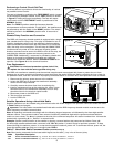

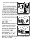
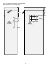

Installing the Earth Ground
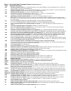
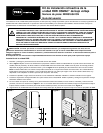
1. Route the green ground wire from the RDR unit transformer
terminal block to the cabinet rear plate. Secure the ground wire
ring terminal to the rear plate using the provided self-tapping
sheet metal screw. See
Figure 6.
2. Remove the lock nut from the lower right corner of the rear
plate. Install the provided star washer, copper ground lug and
lock nut. Tighten securely. See
Figure 6.
3. Connect the copper ground lug to an earth grounding device
using 6 AWG (10mm
2
) bare copper wire. Avoid bends in the
ground wire of less than 8" (20cm) radius.
Important: Make sure the satellite is properly connected to an
earth ground device such as a 5/8" x 8' (16mm x 2.5m) copper clad
rod driven into the earth at a distance from the satellite from 8' to 12’
(2.5–3.7m). The top of the ground rod should be buried 12" (30.5cm)
below grade level. Using an earth ground resistance testing device, a
reading of 0 ohms is optimum, up to 10 ohms is good and 11–30
ohms is acceptable in most cases. If the resistance exceeds the
acceptable limit, an additional ground rod can be installed at a
distance equal twice the length of first rod; i.e., 16' (4.9m). Connect the ground rods using 6 AWG (10mm
2
) bare copper
wire and test again. If the ground resistance remains high, contact your local Toro distributor for further assistance and
recommendations.
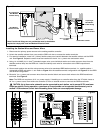
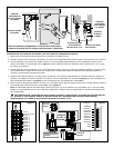
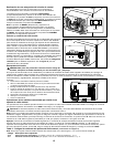
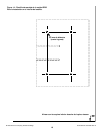
Selecting the Decoder Radio Frequency
The narrow-band frequency decoder module stores four user-
selectable radio frequencies. The frequencies are programmed at
the factory or by the distributor prior to delivery of the RDR unit.
A set of jumper pins, located on the RDR frequency decoder module
enables the frequency to be selected by placing the jumper on the
appropriate channel pin set. See
Figure 7.
The pre-programmed frequencies are as follows:
Channel #1 = 462.2125 MHz
Channel #2 = 462.4375 MHz
Channel #3 = 467.2125 MHz
Channel #4 = 467.4375 MHz
Note: There will be cases where the four pre-programmed
frequencies are not suitable for use in the area. The frequency
programming kit (P/N 102-1208) can be used to program any
available user-defined frequency.
Important: The base station transmitter, hand-held radio and the
RDR frequency decoder module must be set to the same frequency
to enable communication.
Assigning the Satellite Address Number
Each satellite requires a three-digit address number to enable
communication with the central controller and/or a hand-held radio.
The address numbers range from 1 (001) through 255 and is set by
the DIP switches located on the frequency decoder module
assembly. See
Figure 8.
In the down position, the switch is Off (open) and represents a value
of 0 (zero). In the On position, the closed and represents the
following address number:
Sw 1 = 1 Sw 2 = 2 Sw 3 = 4 Sw 4 = 8
Sw 5 = 16 Sw 6 = 32 Sw 7 = 64 Sw 8 = 128
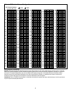
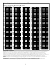
To set the satellite address number, first locate the desired satellite
address in
Table 1 on page 4. Next, position each switch On or Off
as indicated on the chart.
Example: To set satellite address number 50 (050), start with all eight DIP switches in the Off (open) position, then set
switch numbers 2, 5 and 6 to the On position (
2 [2] + 16 [5] + 32 [6] = 50. See Figure 8.
Figure 6
#1
#2
#3
#4
Figure 7
O
12345678
N
Figure 8
Ground Lug
Star Washer
RDR Ground
Connection
6 AWG (10mm
2
)
Wire From Earth
Ground Device
Lock Nut
Transformer
Ground Terminal
3