


™
4
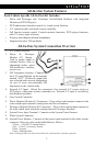
1. Remove the factory headrests (Detailed instructions can be found in the
vehicle’s service manual.
2. Starting with the driver’s side headrest (Monitor A) insert the mini-din
connectors into the driver side headrest post guides.
3. Slowly push the cables into the seat. If an obstruction is encountered, pull
back slightly on the cable and rotate before continuing. Route the cables so
that they exit the bottom of the seatback.
4. Repeat steps 2 and 3 for the passenger’s side headrest (Monitor B).
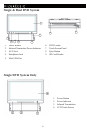
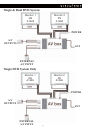
1. Place the A/V Control Module in a well protected area under a seat or behind
a panel.
2. Insert the Monitor's system connector cables into the A/V Control Module.
These connectors will click and lock into place when fully inserted.
3.
Route the monitor and DVD cables from each headrest towards the A/V Control
Module. If additional length is necessary use the available cable extensions.
NOTE: The available extensions are not interchangeable the cable
connector colors must match.
4. Connect these cables from the driver side headrest (Monitor A) to the
DRIVER MONITOR (Monitor A) the A/V Control Module.
5. Connect these cables from the passenger side headrest (Monitor B) to the
PASSENGER MONITOR (Monitor B) on the A/V Control Module.
6. Connect the wireless FM modulator antenna to the connector jack on the
side of the A/V control Module labeled ANT.
7. Extend and route the FM modulator antenna under the carpet or
behind a panel ensuring to avoid any sharp metal edges or moving
parts. For best results do not coil or bundle the FM modulator antenna.
NOTE: If the vehicle has an aftermarket radio that accepts RCA auxiliary inputs
or the use of a wireless FM modulator is not desired, simply remove the modulator
antenna and connect RCAs to the Driver Monitor A/V Output (located on the side of
the A/V control module) and route them to the desired component.
8. Plug the power harness into the A/V control module and connect the power
wire leads to 12V+ and 12V ground. The wires are color coded as follows:
Red = ACC Power, Yellow = Constant Power, Black = Ground, Green =
Parking brake.