


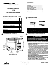
MOUNTING AND WIRING
Take care when securing and routing wires so they do
not short to adjacent terminals or rear of thermostat.
Personal injury and/or property damage may occur.
CAUTION
!
ATTENTION! This product does not contain mercury. How-
ever, this product may replace a unit which contains mercury.
Do not open mercury cells. If a cell becomes damaged, do not
touch any spilled mercury. Wearing non-absorbent gloves, take
up the spilled mercury and place into a container which can be
sealed. If a cell becomes damaged, the unit should be discarded.
Mercury must not be discarded in household trash. When the unit
this product is replacing is to be discarded, place in a suitable
container and return to White-Rodgers at 2895 Harrison Street,
Batesville, AR 72501-2117 for proper disposal.
REMOVING OLD THERMOSTAT
CONTINUED FROM FIRST PAGE
WARNING
!
Do not use on circuits exceeding specified voltage.
Higher voltage will damage control and could cause
shock or fire hazard.
Do not short out terminals on gas valve or primary
control to test. Short or incorrect wiring will damage
thermostat and could cause personal injury and/or
property damage.
Thermostat installation and all components of the sys-
tem shall conform to Class II circuits per the NEC code.
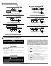
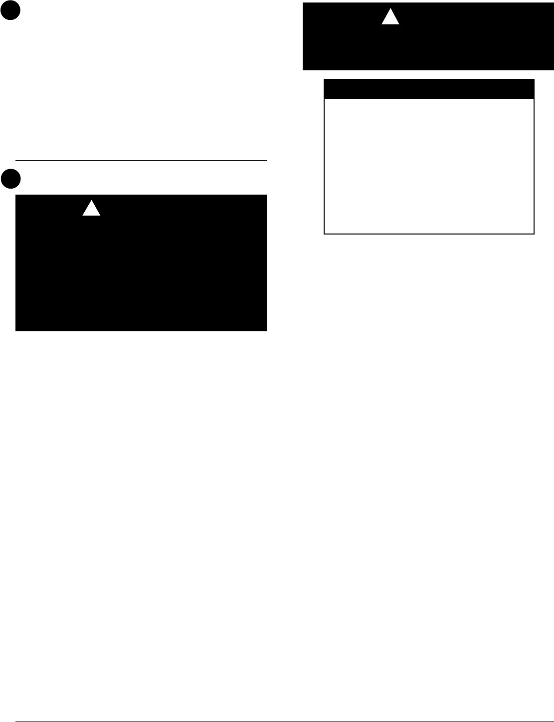
TERMINAL CROSS REFERENCE CHART
New Thermostat
Terminal Designation
Other Manufacturers’
Terminal Designation
RH
RC
G
W
Y
4
R
G
W
Y
RH
R
G
W
Y
M
V
F
H
C
R5
-
G
4
Y6
R
-
G
W
Y
**
* These are four-wire, single-transformer systems.
Factory installed jumper wire between the RH
and RC terminals must remain in place.
www.white-rodgers.com
4
3
Electric Heat or Single-Stage
Heat Pump Systems
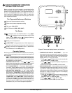
This thermostat is configured from the factory to operate a heat/
cool, fossil fuel (gas, oil, etc.), forced air system. It is configured
correctly for any system that DOES NOT require the thermostat
to energize the fan on a call for heat. If your system is an electric
or heat-pump system that REQUIRES the thermostat to turn on
the fan on a call for heat, locate the GAS/ELECTRIC switch (see
fig. 1) and switch it to the ELECTRIC position. This will allow the
thermostat to energize the fan immediately on a call for heat. If you
are unsure if the heating/cooling system requires the thermostat
to control the fan, contact a qualified heating and air conditioning
service person.
Hydronic (Hot Water or Steam)
Heating Systems
This thermostat is set to operate properly with a forced-air heating
system. If you have a hydronic heating system (a system that
heats with hot water or steam), you must set the thermostat to
operate properly with your system.
The factory default setting is forced air heat. Clipping jumper
W905 on the circuit board will produce a longer heating cycle
which is normally for hot water or steam (hydronic) systems. Both
settings produce a very accurate temperature control and can be
set to your personal preference. As received, the thermostat
cycles the system just under 1˚F. With W905 clipped, the system
cycles at approximately 1.5˚F.
Attach Thermostat Base to Wall
1. Remove the packing material from the thermostat. Gently pull
the cover straight off the base. Forcing or prying on the
thermostat will cause damage to the unit. If necessary, move
the electric heat switch (see ELECTRIC HEAT SYSTEMS,
above).
2. Connect wires beneath terminal screws on base using appro-
priate wiring schematic (see figs. 2 through 7).
3. Place base over hole in wall and mark mounting hole locations
on wall using base as a template.
4. Move base out of the way. Drill mounting holes.
5. Fasten base loosely to wall, as shown in fig. 1, using two
mounting screws. Adjust until level, and then tighten screws.
(Leveling is for appearance only and will not affect thermostat
operation.) If you are using existing mounting holes, or if holes
drilled are too large and do not allow you to tighten base
snugly, use plastic screw anchors to secure subbase.
6. Push excess wire into wall and plug hole with a fire-resistant
material (such as fiberglass insulation) to prevent drafts from
affecting thermostat operation.
Battery Location
This thermostat requires 2 “AAA” alkaline batteries to operate.
If “LO BATTERY” is displayed, the batteries are low and should
be replaced with fresh “AAA” Energizer
®
alkaline batteries. To
replace the batteries, install the batteries along the top of the base
(see fig. 1). The batteries must be installed with the positive(+)
ends to the right.