


CHECK THERMOSTAT OPERATION
www.white-rodgers.com
5
RH
24 VAC
120 VAC
Hot
Neutral
THERMOSTAT
SYSTEM
G W
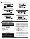
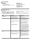
Figure 2. Typical wiring diagram for
heat only, 3-wire, single transformer systems
TRANSFORMER
Heating
System
Fan
Relay
Y
RC
JUMPER
WIRE
OB
For 2-wire Heat only,
attach to RH and W
NOTE
RH
Y
24 VAC
120 VAC
Hot
Neutral
TRANSFORMER
THERMOSTAT
SYSTEM
G W
Figure 3. Typical wiring diagram for
cool only, 3-wire, single transformer systems
Cooling
System
Fan
Relay
RCOB
JUMPER
WIRE
RH
Y
24 VAC
120 VAC
Hot
Neutral
THERMOSTAT
SYSTEM
G W
Figure 4. Typical wiring diagram for
heat/cool, 4-wire, single transformer systems
TRANSFORMER
Heating
System
Fan
Relay
Cooling
System
RC
JUMPER
WIRE
OB
RED jumper wire (provided with thermostat) must be
connected between thermostat RH and RC terminals
for proper thermostat operation with this system.
NOTE
RH
Y
24 VAC
120 VAC
Hot
Neutral
THERMOSTAT
SYSTEM
G W
Figure 5. Typical wiring diagram for
heat/cool, 5-wire, two-transformer systems
HEATING
TRANSFORMER
Heating
System
Fan
Relay
Cooling
System
RC
24 VAC
120 VAC
Hot
Neutral
COOLING TRANSFORMER
OB
RH
Y
24 VAC
120 VAC
Hot
Neutral
THERMOSTAT
SYSTEM
G W
Figure 6. Typical wiring diagram for heat pump
with reversing valve energized in COOL
TRANSFORMER
Reversing
Valve*
RCOB
JUMPER
WIRE
Compressor
Contactor
JUMPER
WIRE
* Reversing valve is energized when the
system switch is in the COOL position
Fan
Relay
RH
Y
24 VAC
120 VAC
Hot
Neutral
THERMOSTAT
SYSTEM
G W
Figure 7. Typical wiring diagram for heat pump
with reversing valve energized in HEAT
TRANSFORMER
Reversing
Valve*
RCOB
JUMPER
WIRE
Compressor
Contactor
JUMPER
WIRE
* Reversing valve is energized when the
system switch is in the HEAT position
Fan
Relay
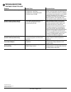
NOTE
To prevent static discharge problems, touch side of ther-
mostat to release static build-up before touching any keys.
If at any time during testing your system does not operate
properly, contact a qualified serviceperson.
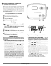
Fan Operation
If your system does not have a G terminal connection, skip to
Heating System.
1. Turn on power to the system.
2. Move FAN switch to ON position. The blower should begin to
operate.
3. Move FAN switch to AUTO position. The blower should stop
immediately.
This thermostat has a time delay between cooling cycles to allow
the head pressure in the compressor to stabilize. If the tempera-
ture is adjusted to call for cool within 5 minutes of the last cycle the
snowflake icon will blink indicating the thermostat is locked out.
After 3 to 5 minutes, the compressor will start and the snowflake
icon will stop flashing. This helps prevent the compressor from
cycling too quickly and is normal operation for the thermostat.
1. Move SYSTEM switch to COOL position.
2. Press
to adjust thermostat setting below room tempera-
ture. The blower should come on immediately on high speed,
followed by cold air circulation
3. Press to adjust temperature setting above room tem-
perature. The cooling system should stop operating.
Heating System
1. Move SYSTEM switch to HEAT position. If the heating system
has a standing pilot, be sure to light it.
2. Press to adjust thermostat setting above room tempera-
ture. The heating system should begin to operate.
3. Press to adjust temperature setting below room tem-
perature. The heating system should stop operating.
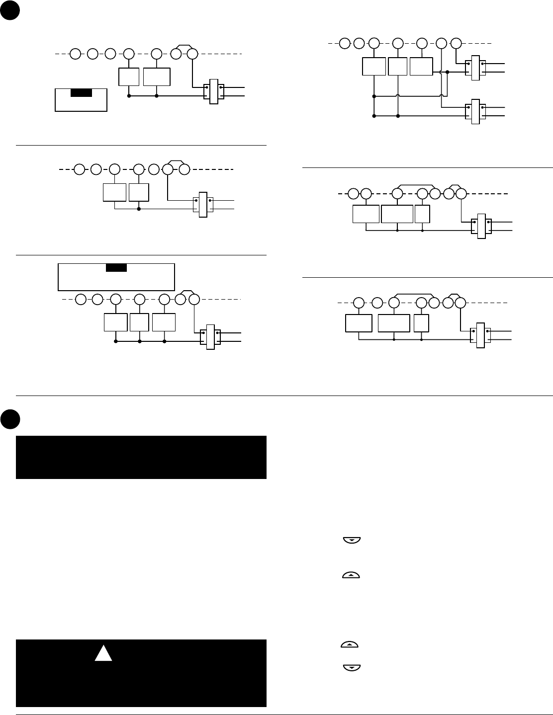
To prevent compressor and/or property damage, if the
outdoor temperature is below 50°F, DO NOT operate the
cooling system.
CAUTION
!
Cooling System
MOUNTING AND WIRING
CONTINUED FROM SECOND PAGE
4