


FIELD SERVICE NOTE FOR: NX520P & EF500P May 27, 2002
We have experienced some failures with the short pilot runs of 520P and EF500P due to
an incorrectly mounted resistor on the power board. There are only about a dozen of each of
these in each of our market territories. These failures at first sight will seem somewhat
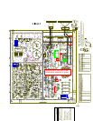
intimidating due to the blackening soot which is produced when the resistor arcs out to the
printed high voltage rails under the resistor designated R60. The damage looks far worse than it
really is and is generally repairable by anyone with basic electronics and soldering skills.
The greatest difficulty with servicing class “D” amplifiers is that most service people
have never serviced one before. And, like all things new, they don’t like being in unfamiliar
water. When you have done a couple of these kinds of amps, you will realize that they are
probably easier to repair than their linear counterparts. But there are two dramatic differences to
be observed in testing this class of amp. They are:
1) You cannot soft start this type of amplifier as it has an error amplifier, which will deny start
up at low voltage.
2) You must have a load connected to the output upon startup. The amp sends a test pulse upon
startup which must be registered in the feedback loop before it will activate the driver chip. If
there is no load there is no current in the output, if there is no current, there is no voltage and
consequently no feedback pulse.
The good news is that this class of amp will generally not cook off if you failed to repair it and
then try to fire it up. It usually just sits there dumbfounded waiting for you to find the missing
faulty bits.
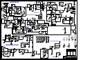
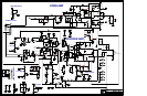
The process for repair of units suffering from an R60 arc over is as follows.
A) Remove the remains of R60 and clean the soot from the board. Please remember this is a
double-sided circuit board with thru plated component holes. Do not use excess force to
remove the component leads from their solder holes. They will come out easy enough when
you have enough heat on the joint.
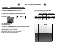
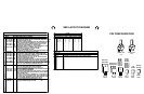
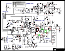
B) Replace the following components : 1) Q15 , IRFP350 2) Q17 , 2N5551 3) U10 ,
74HC14N 4) U8 , IR2110 And finally, R60 , 1K5 , which should be installed about ¼”
above the board so as not to arc out to the high voltage traces again.
C) Measure the following parts; just to be sure we don’t have any stragglers. 1) R58, .47ohms
2) R50 , 75R 3) R65 , 1K and 4) D20 , 18 volt zener.
D) Yorkville Part #’s (Q15 = 6914) (Q17 = 5107) (U10 = 6603) (U8 = 6887) (R60 = 2034)
When all the bits have been replaced and the other parts measured, you are ready to fire it up.
Do not forget the startup rules mentioned above and you should have a 95% chance of a first
shot success on the job.
Address any further questions to: Guy Beresford (gberesford@yorkville.com) or 905-837-8481
extension 236.