


SERVICE BULLETIN
SERVICE BULLETIN
2
2
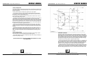
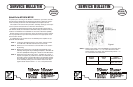
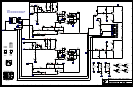
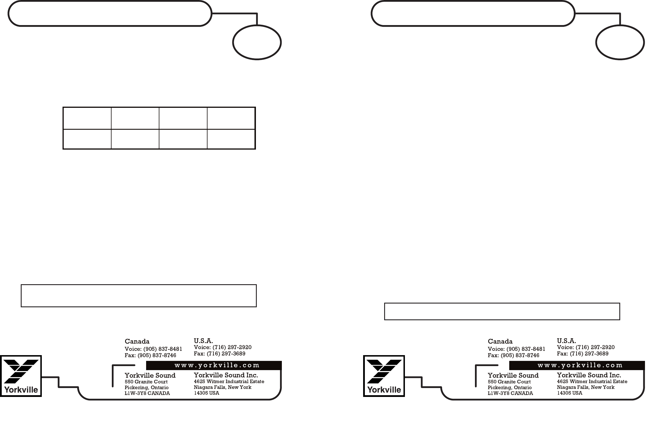
STEP 6. Measure across the pair of test points shown in the component
layout listed in the table below. If the measured value is not
within + or – 10% of the value listed in the table then replace
the resistors shown in the table below.
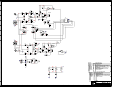
STEP 7. Measure the resistors coloured ORANGE. Since the value of
these resistors is 0.1 ohm, your ohmmeter will measure the
higher series resistance of the test leads if the resistor is OK. If
the resistor is damaged your ohmmeter will read a very high
resistance (an open circuit). Replace any damaged resistors.
STEP 8. Measure the output TO–3 transistors (Q13 to Q28) to deter-
mine if any are damaged. Mark any damaged transistors with
a marking pen.
STEP 9. Replace any output transistors that you have marked as being
damaged. Replace any diodes that you have found to be dam-
aged. Replace all of the red transistors that were removed.
STEP 10. Inspect the traces on the circuit board for any that have ‘fused’
open or looklike they got very hot. Bridge and solder a piece of
wire over any damaged traces.
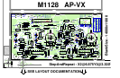
Testing Repaired Circuit Boards
Now that you have rebuilt the M1146 or M1126 circuit board. It is just as
important to properly power up the board. If the sinewave doesn’t look right
check the signal at test point (1) to ensure that the voltage amplifier isn’t dis-
torting the signal. If there is still a damaged part on the board instantly turn-
ing it on could blow up the board and you would be back where you started.
Connect the power wires and ground to the power supply. Connect a digi-
tal multimeter to test pins 8 and 9 to measure the bias quiescent current
and place a scope probe on the speaker output. Be sure to turn the quies-
cent current trimpot RT1 fully counter clockwise.
Now using a variac slowly turn up the AC main voltage while monitoring
the quiescent voltage and the speaker output trace on the scope. Watching
these two test points is a good indicator of the health of the board. If you
have a second multimeter connect it up from the speaker output to test
point 4 or 5. As you variac up also check these DC battery voltages to
ensure that they both increase in voltage to approximately +12 or –12 vdc.
If the board looks OK after variacing up to 120vac then slowly turn up the
bias (RT1 trimpot) to obtain 3 to 5 millivolts of bias voltage on test points 8
and 9. Check the speaker output with a 1KHZ sinewave with no load. If this
looks good place the minimum rated load (4 Ohm for M1126, 2 Ohm for
M1146) on the speaker output and increase the sinewave amplitude to the
point of clipping. If the signal looks free of oscillation, place a short across
the speaker posts. The amplifier should go into protect mode after 1/10 of a
second. Remove the short and the sinewave will appear 6 seconds later.
Reassemble the complete amplifier and run just clipping music or pink
noise into the minimum rated speaker load for that model of amplifier. Let
the amplifier heat up for 20 minutes. This will check the thermal mounting of
the transistors and for any weak parts not caught during troubleshooting.
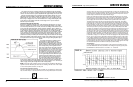
TEST
POINTS
R10
LAYOUT
REFERENCE
4K7
LAYOUT
REFERENCE
R11, R12, R14
CORRECT
MEASURED
VALUE
-10%
15ohm
17ohm
+10%
19ohm
AP4020 &
AP4040
AP4020 &
AP4040
AFTER YOU HAVE REPLACED ALL OF THE NECESSARY COMPONENTS INSPECT
THE REPAIRED BOARD FOR ANY MISSING PARTS, CORRECT VALUES IN THE COR-
RECT POSITION AND THAT ALL COMPONENTS ARE SOLDERED.
If the amplifier passes this test the product is ready to
return to the customer.