550 Granite Court, Pickering, Ontartio CANADA L1W-3Y8
4625 Witmer Industrial Estate, Niagara Falls, New York USA 14305
SERVICE MANUAL
4
Yorkville Sound • http://www.yorkville.com
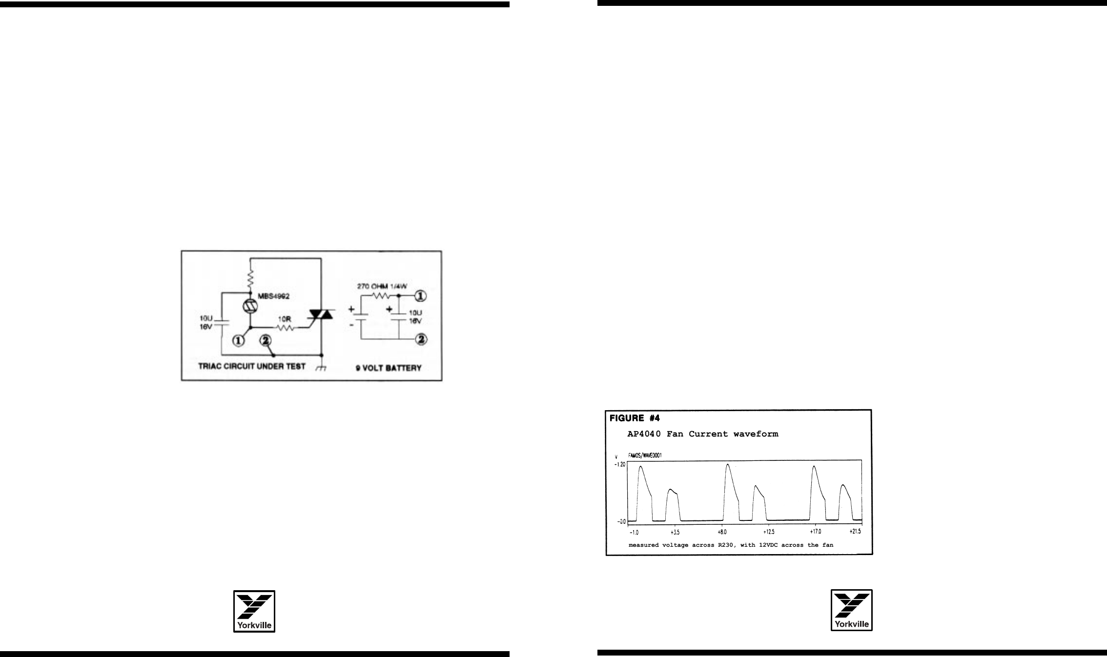
NOTE: Every time you replace blown output transistors on a
M1146 board test the DC protection triac with the following circuit.
Conditions of test:
A) Pass a 100Hz 25v peak signal through the M1126 board under test with no load
connected to the amplifier output.
B) Connect points 1 and 2 as shown in the diagram. The amplifier should go into pro-
tect mode as the triac (if working) shorted the output of the amplifier to ground, and
the amplifier goes into current limit.
C) Disconnect the triac test circuit and allow the amplifier to complete it’s protect cycle.
D) Reverse connections 1 to 2 and 2 to 1 and test again. The same results as in B)
should be observed if the triac is working.
Only test the triac for one protect cycle as
prolonged testing will heat the triac to a high temperature.
MM11114477 SSHHUUTTDDOOWWNN CCIIRRCCUUIITT,, FFAANN CCOONNTTRROOLL CCIIRRCCUUIITT,,
aanndd SSOOFFTT TTUURRNN OONN CCIIRRCCUUIITT::
• The shutdown relay and its associated drive circuitry have two possible
operating states.
• Amplifier on under normal operating conditions.
• Amplifier power switch has just been turned OFF/ON, or the amplifier is in current
limit protecting the amplifier’s output transistors, or the amplifier has overheated.
Shutdown Circuit
Here is how the circuit accomplishes these functions. The relay’s normally closed con-
tacts short the output of the voltage amplifiers to ground when the power switch is off.
When the power switch is turned on, the relay remains off (normally closed) for about
6 seconds. C203 charges to 35V and results in Q203 turning off allowing Q201 to turn
on. As Q201 turns on, it connects the negative terminal of the relay’s coil (Pin 16) to
ground energizing the relay and opening the normally closed contacts.
550 Granite Court, Pickering, Ontartio CANADA L1W-3Y8
4625 Witmer Industrial Estate, Niagara Falls, New York USA 14305
SERVICE MANUAL
Yorkville Sound • http://www.yorkville.com
If prolonged current limiting occurs on the amplifier’s output transistors then D204 or
D205 (depending on which channel is current limiting) will be forward biased turning on
Q202 (from its off state). Now +144VDC appears on the collector of Q202 and through
R210 and R211 turn on Q203 therefore turning off Q201 by shorting its base emitter
junction. Q201 turning off will turn the relay off and the normally closed contacts (off
state) will short the outputs of the voltage amplifiers to ground so as not to continuously
stress the amplifier’s output transistors. A cycle now occurs. With the voltage amplifiers
now disabled there is no signal driving the output transistors (Q13 to Q28).
The current limit circuit protecting the output transistors (Q13 to Q28) turns off and
D204 and/or D205 are not forward biased and Q202 turns off. Through Q203 and
Q201 the relay is turned back on and the voltage amplifiers are now active again, dri-
ving the output transistors. If current limiting still occurs, then the same cycle will occur.
If the cause of current limiting (low impedance or short on the speaker output termi-
nals) has been removed, then the amplifier will continue to operate normally.
The third operation that the relay provides is “overheat shutdown”. If for some rea-
son the fan cannot keep the heatsinks in a safe operating temperature area then the
fan control circuit (on board M1147) will deliver through D207 a positive current to turn
Q203 on and turn Q201 off to turn off the relay and disable the voltage amplifiers.
When the fan has cooled down the temperature of the amplifier, then the signal
through D207 will disappear and the relay circuit will turn on the relay to resume nor-
mal operation. Anytime the relay is in the “protect” mode (due to the abnormal states)
then contact pin 4 of the relay will illuminate LD3 (the protect LED on the front panel).
Soft Turn On Circuit
To reduce the “inrush” current that flows through the line cord from the 120 VAC power
source (typical with large linear power supplies), a circuit provides a soft turn on func-
tion. When the power switch is turned on, the current that initially flows through the pri-
mary of the transformer must flow through SG201 and SG202. These are surgestors
that reduce the peak inrush current flow. After about 500 milliseconds a relay’s con-
tacts short across the surgestors so that they are not stressed by the current flowing
through them under normal operation. A circuit consisting of Q240, Q241, C215, and
the associated resistors provides the time delay for the turn on cycle of the relay. The
circuit is very similar to the shutdown time delay circuit. Refer to the section on the
shutdown circuit for a circuit description.
Fan Circuit
Looking at the schematic to board M1147, here is a
quick explanation of the fan control circuit. There is
a temperature sensor (AS35) on each M1146
board. When the amplifier is first turned on, Q207
and Q208 are off. The AS35 temperature sensors
are configured as temperature controlled current
sources. As either temperature sensor begins to
heat up, more current flows through D212 or D218
increasing the voltage drop across R235 or R236.
The hotter temperature sensor will provide more
current than the cooler sensor and therefore devel-
op a higher voltage across it’s associated 8K2
resistor. The higher voltage will forward bias D212
or D218 reverse biasing the cooler temperature
sensor’s diode so that the hotter sensor will control the fan speed. At 40 degrees C there
4


