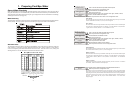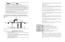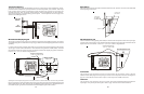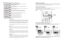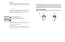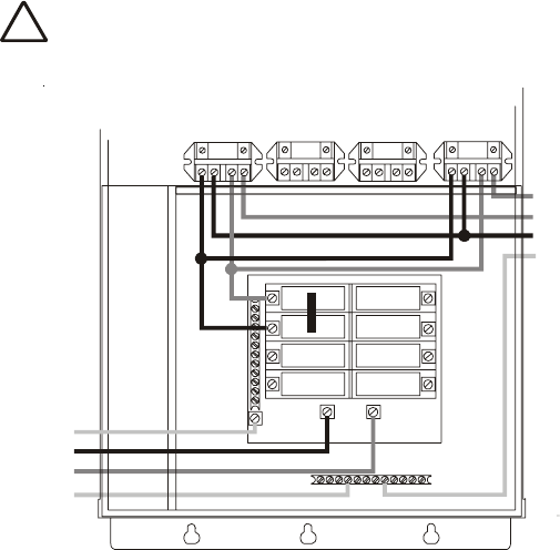
Two speed filter pump: Requires 2 relays (FILTER plus one of the AUX relays) for proper operation of
both speeds.
IMPORTANT: Be sure to follow the wiring diagram below AND to configure
the control logic according to the instructions on page 25.
Lights: A ground fault circuit breaker must be used to supply power for high voltage pool/spa lighting.
Low voltage lights will require an external transformer. For lighting systems that have both a light source
and color wheel, connect the light source to the “Lights” relay and then connect the color wheel to one of
the AUX outputs.
Low Voltage Wiring
Valve Actuators
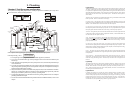
The Aqua Logic can control up to four (PS-4/8) or eight (PS-16) 24V automatic valve actuators. Two of
the valve outputs are dedicated to the pool/spa suction (Valve2) and return (Valve1) valves. Valve3 and
Valve4 (Valves3, 4, 7-10 for PS-16) are for general purpose use (solar, water feature, in-floor cleaner,
etc.).
For installations with solar heating, Goldline offers the AQ-SOL-KIT-xx solar kit that contains a valve,
actuator, and extra temperature sensor. The “xx” indicates the valve type from the 2 choices below:
-1P 1.5” Positive Seal
-2P 2” Positive Seal
The Aqua Logic is compatible with standard valve actuators manufactured by Hayward, Pentair/Compool,
and Jandy. See diagram on page 13 for the location of valve connectors.
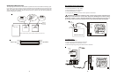
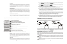
Heater Control
The Aqua Logic allows for independent control of up to 2 heaters plus a solar heating system if applicable.
A typical use for this feature is on a pool that has both a gas heater (for rapid heating of the spa) and a heat
pump (for economical heating of the pool). IMPORTANT: If you chose to use the “Heater2” control
output, then you will not be able to use the “Valve4” output. These 2 functions use the same internal
relay and only one can be enabled. In the configuration menu, if “Heater2” is enabled, then the configura-
tion for “Valve4” will never appear. The heater interface wiring, as described below, is identical for “Heater1”
and “Heater2” except for the terminal connections at the Aqua Logic control.
The Aqua Logic provides a set of low voltage dry contacts that can be connected to most gas heaters or
heat pumps with 24V control circuits. Refer to the diagram on the following page for a generic connection.
15
2-Speed
Filter
Pump
G
L1
L2
Lo Speed
Hi Speed
Common
Ground
24
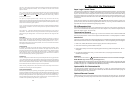
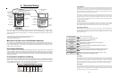
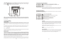
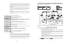
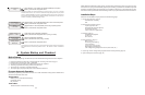
To access the Configuration Menus
Configuration
Menu-Unlocked
Configuration
Menu-Locked
Press repeatedly until “Configuration Menu” is displayed
Move to configuration menu items
Press BOTH buttons SIMULTANEOUSLY for 5 seconds to unlock
Menu
>
>
>
>
NOTE: The configuration menu automatically “locks” after 2 minutes of no buttons being
pressed to prevent unauthorized people from changing the control logic inadvertently and
possibly damaging the pool equipment or causing a “call back” to fix the configuration.
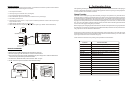
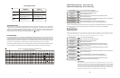
Configuration Menus
Each item needs to be programmed and may contain additional sub-menu items. Refer to the following
pages for information on programming.
Toggle between T-CELL-5 and T-CELL-15
>
>
Chlorinator
Enabled
Display
Salt
Chlor. Config.
+ to view/change
Toggle between Enabled (default) and Disabled
Chlorinator
Toggle between Display Salt (default) and Minerals
Move to next menu item
Move to previous/next configuration menu
Move to next configuration menu
>
>
>
Push to access Chlorinator option
Chlorinator
If the chlorinator is enabled (requires the use of the AQL-CL chlorination kit), then the cell
and flow switch must also be installed and the Aqua Logic will automatically chlorinate both
the pool and spa according to the desired output setting (see Settings Menu in the Operation
manual). If disabled (default), then neither the cell nor flow switch need to be installed and
all displays relating to the chlorinator will be suppressed.
When the chlorinator is enabled, the Aqua Logic will automatically detect and control any
Aqua Rite(s) that is installed in the system (see page 21).
Display
Allows for the display of salt (default) or mineral values.
Cell Type Selection
The Cell Type Menu appears after “Display Salt/Minerals” in the Chlorinator Configuration
Menu. The options are T-CELL-5 or T-CELL-15 (default). Make the proper selection based
on the electrolytic cell that is used in your system. For pools up to 20,000 gallons, the T-
CELL-5 is typically used. The T-CELL-15 is for pools up to 40,000 gallons.