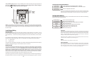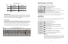
Raypak RP2100 Pool/Spa Heater
1. Turn power off to heater.
2. Push the mode button to “spa” mode.
3. Set the temperature to the maximum.
4. Push the mode button to “OFF”.
5. Lastly, plug the prewired connector in the P7 position on the board.
IMPORTANT: The heater will display “OFF” when it is being remotely controlled by the
Aqua Logic. Some homeowners see the “OFF” display and, thinking this is a mistake, change
the mode to “POOL” or “SPA” which then disables the remote control by the Aqua Logic. To
prevent this: Remove the heater touch pad connector (P5) which will disable the touchpad.
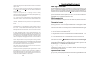
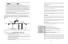
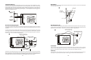
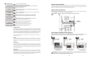
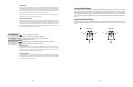
STA-RITE Heater
1. Turn power off to heater.
2. Remove upper jacket and open the control box.
3. Remove the jumper for the “fireman’s switch.
4. Wire to the Aqua Logic using wire rated for 105°C minimum.
18
STA-RITE
Ter mi nal
Board
Operating
‘Control PCB
Fireman’s
Switch
ir
Solar
P7
Yellow/Bl ack
Black
Orange Stripe
Orange
StripeBlack
RAYPAK RP2100
ir
Solar
21
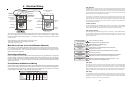
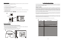
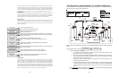
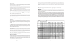
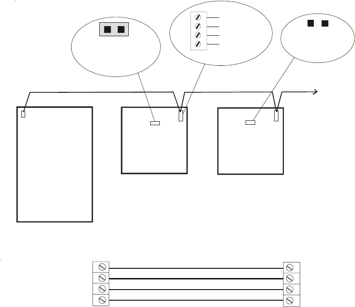
Goldline Aqua Rite Chlorinator
The Aqua Logic can control one or more Goldline Aqua Rite chlorinators when additional sanitizing capac-
ity is required. A 4 wire connection is used to communicate to the Aqua Rite and can be wired up to 500'
apart. Any outdoor rated 4 conductor cable can be used. Refer to the wiring diagrams below for proper
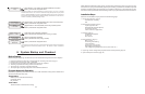
wiring connection to the Aqua Rite. NOTE: There must be only 1 "primary" unit. All other Aqua Rite units
must be configured as "secondary".
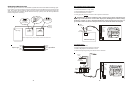
4
3
2
1
GRN
BLK
YEL
RED
Aqua Logic
Aqua Rite
green
yellow
black
red
Aqua Logic
Aqua Rite
(Primary)
Aqua Rite
(Secondary)
qua Rite(s)
(if required)
Jumper Removed
For Secondary(s)
Jumper Installed
For Primary
(Factory Default)
1
2
3
4
GREEN
NOTE: Primary/Secondary jumper is located underneath small circuit board.