EPSON Stylus COLOR 3000
Rev. A
2-1
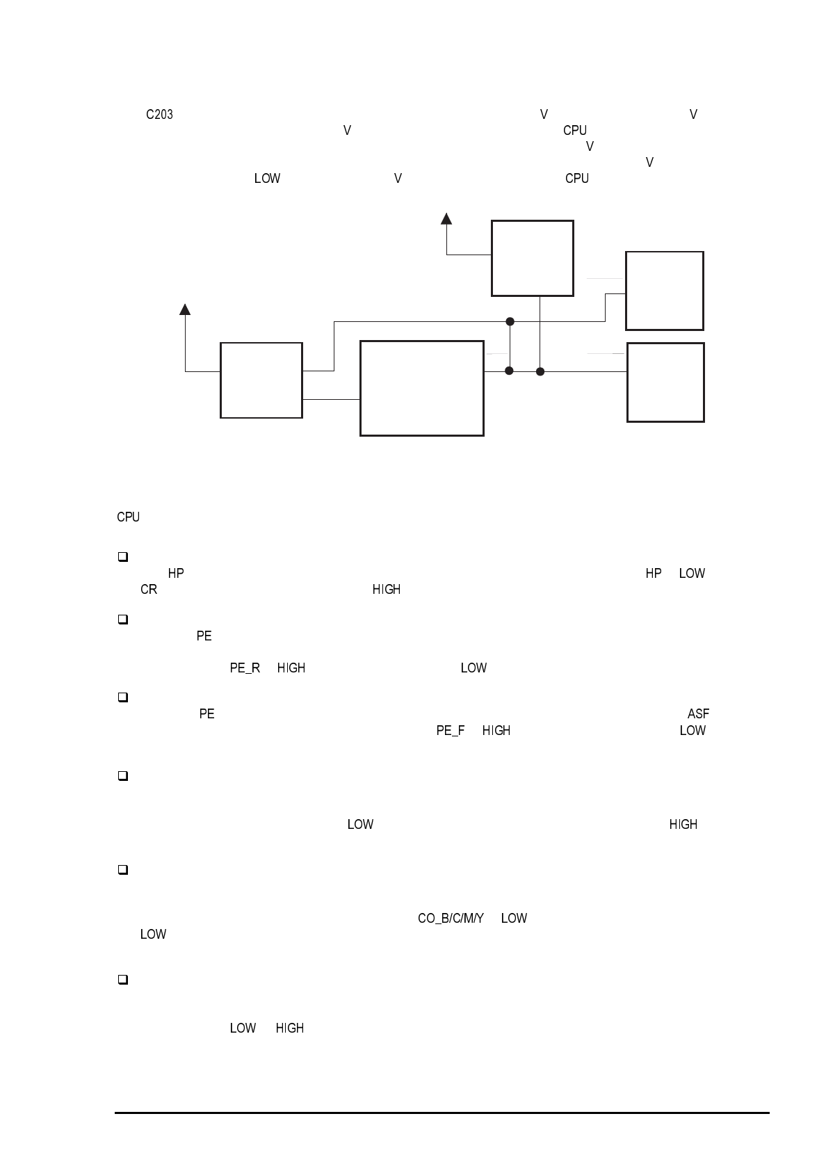
2.3.2.1 Reset Circuits
The MAIN board contains two reset circuits: for logic line (+5 ) and power line (+42 ). Reset IC
M51955BFP (IC3) monitors the +42 line. It outputs /NMI signal to the and the gate array to cut off
the power line for the motors when the voltage level drops below 33.2 . Reset IC RST592D (IC9)
monitors the +5 V line and sends low pulse when the voltage level drops below 4,2 . While the printer
power is on, it outputs until stabilized +5 is produced to ensure the ’s proper operation.
2.3.2.2 Sensor Circuits
and the gate array E05B45 (IC 16) monitor printer condition referring to the signals from 13 sensors
described below
HP : Output from the HP(Home Position) sensor.
The sensor for this printer uses the reliable photo interrupter system. the signal is when the
unit is at the home position, and is when it is not at the home position.
PE_R : Output from the rear PE (Paper End) sensor.
The rear sensor, attached to the rear part of the paper path, detects paper presence condition for
continuous paper or cut sheet set in the rear paper slot. A mechanical switch is used for this sensor
and the signal is with paper detected and without any paper detected.
PE_F : Output from the front PE (Paper End) sensor.
The front sensor, located in the paper guide unit, detects paper presence condition for . This
sensor uses a mechanical switch and the signal is with paper detected and is without
any paper detected.
REL : Output from the release sensor.
Release sensor is built into the rear part of the left frame in the printer mechanism. It determines
whether the release lever is set to the cut sheet side (friction mode) or to the continuous paper side
(tractor mode). The signal REL is when the lever is set to the friction mode and is when the
lever is set to the tractor mode.
CO_B/C/M/Y :Output from each ink cartridge sensor.
The ink cartridge sensor for each color is individually attached to the ink cartridge holder in the printer
mechanism. It determines whether the corresponding ink cartridges is installed or not. A mechanical
switch is used for this sensor and the signals is when the cartridge is installed and is
when the cartridge is not installed. When the sensor detects no cartridge condition, the ink
consumption counter is reset.
IE_B/C/M/Y : Output from each ink end sensor.
The ink end sensor for each color, individually attached to the ink cartridge holder in the printer
mechanism, detects ink end condition*. It uses the mechanical switch system and the signal
IE_B/C/M/Y
is or on the ink left or end condition, respectively. If the ink end condition is
detected while the ink cartridge is detected by the ink cartridge sensor, the ink consumption counter is
reset.
Note) The ink end sensor detects an ink end condition when the remainder of the ink drops to 5 % of
the capacity.
RST592D
(IC9)
M51955BFP
(IC3)
CPU
H8S/2655
(IC5)
GA
E05B33
(IC6)
GA
E05B45
(IC16)
+5V
+42V
VOUT
RESET
NMI
RES
RESET
OUT
NC5
Figure 2-16. Reset Circuit Block Diagram


