RGB 202 R
xx
xx
x
ii
ii
i, RGB 202 R
xx
xx
x
ii
ii
i
VTG • Installation and Operation
RGB 202 R
xx
xx
x
ii
ii
i, RGB 202 R
xx
xx
x
ii
ii
i
VTG • Installation and Operation
Installation and Operation, cont’d
Most laptop or notebook computers have an external
video port, but they require special commands to output
the video to that connector. Also, laptops’ screens shut
off once that port is activated. See the computer’s user’s
guide for details, or contact Extron for a list of laptop
keyboard commands.
2. Connect the unbalanced stereo audio sources (computer or
other devices such as a CD player) to
the front panel.
Wire the audio jack as shown here.
3. Connect the display device’s (projector’s, monitor’s)
coaxial BNC cable to the rear panel BNC connectors.
For RGBHV (separate H and V sync) output,
connect the cables as shown at left.
For composite sync (RGBS), connect the sync
cable to the connector labeled “S”.
For sync on green (SOG, RGsB), connect the
cables as shown here, and also select the SOG
option on the rear panel DIP switch.
4. Connect the local monitors to the monitor breakout cables
if they were used in step 1 to connect the computers to the
interface. Set the 75 ohm DIP switches to On if no local
monitor is used with a connected MBC cable.
5. Connect an audio device, such as powered speakers, to the
rear panel stereo audio output connector for balanced or
unbalanced audio output. Following the wiring guide
shown below, insert the wires into the appropriate
openings in the captive screw connector. Tighten the
screws on top to fasten the wires, then insert the wired
audio connector into the audio output connector on the
interface rear panel.
For unbalanced output, connect the sleeve to
ground (GND). Connecting the sleeve to a negative
(-) terminal will damage the audio output circuits.
Unbalanced Output
AUDIO
AUDIO
Tip
See Warning
Sleeve (s)
Tip
See Warning
Balanced Output
Tip
Ring
Sleeve (s)
Tip
Ring
LR
LR
Wiring the audio output connector
RGB 202
R
RS-232 Control
System or
Computer
Laptop Computer
Sun Workstation
MBC Buffer
CRT Projector
Stereo Audio
H
i C
a
ro
l
Hi
C
a
ro
l
DDSP
SOG
SERR
NEG SYNC
V SYNC WIDTH
75 OHM 1
75 OHM 2
NO BACKLIGHT
A
U
DIO
INP
UT
P
O
W
ER
M
B
C
R
EM
O
TE
1
12
2
AN
AL
OG
1
0
0
-
2
4
0
0
.
2
A
5
0
/
6
0
H
z
OUTPUTS
INPUTS
R
H
G
V
B
S
A
N
ALO
G
OUTPUT
9VDC
RGB 202 R
xixi
xixi
xi
/
RGB 202 R
xixi
xixi
xi
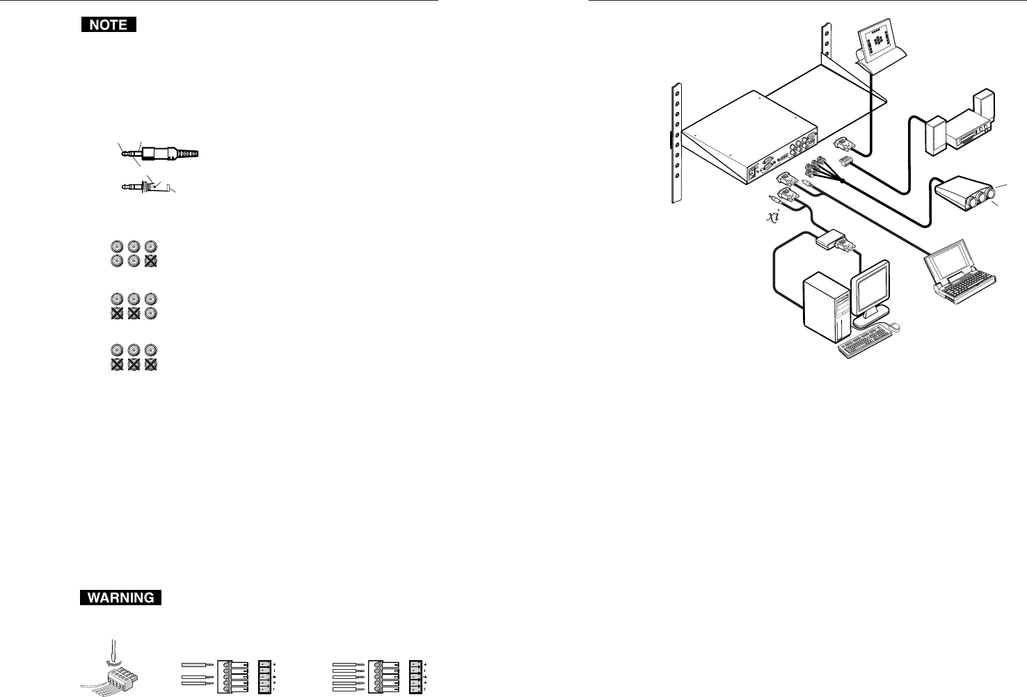
VTG application diagram
6. Set the interface’s DIP and toggle switches. Use the “Rear
Panel” section of this chapter as a guide.
7. Connect an RS-232 control device, if one will be used.
8. Connect power cords and turn on the display and audio
output devices (projectors, monitors, speakers), interface,
and input devices (computers). The system is ready for
operation.
2-132-12
RGBHV
R
H
G
V
B
S
RGBS
R
H
G
V
B
S
RGsB
R
H
G
V
B
S
L) Sleeve (GND)
Tip (L)
Ring (R)
Sleeve (


