12. POSITION SWITCH
12.1 Outline of Function
II - 305
Position switch numbers of PSW1 to PSW24 and signal devices
<axis> <dog1> <dog2> <check> device
PSW1 #7501 #7502 #7503 #7504 X270
PSW2 #7511 #7512 #7513 #7514 X271
PSW3 #7521 #7522 #7523 #7524 X272
: : : : : :
PSW8 #7571 #7572 #7573 #7574 X277
PSW9 #7581 #7582 #7583 #7584 X328
PSW10 #7591 #7592 #7593 #7594 X329
: : : : : :
PSW24 #7731 #7732 #7733 #7734 X337
Instead of the dog switch provided on the machine axis‚ the coordinate values indicating imaginary dog
positions (dog1 and dog2) on the coordinate axis of the axis name preset with axis are set with the position
switches (PSW1 – PSW24). When the machine reaches the position‚ the signal is output to the device
corresponding to the PLC interface.
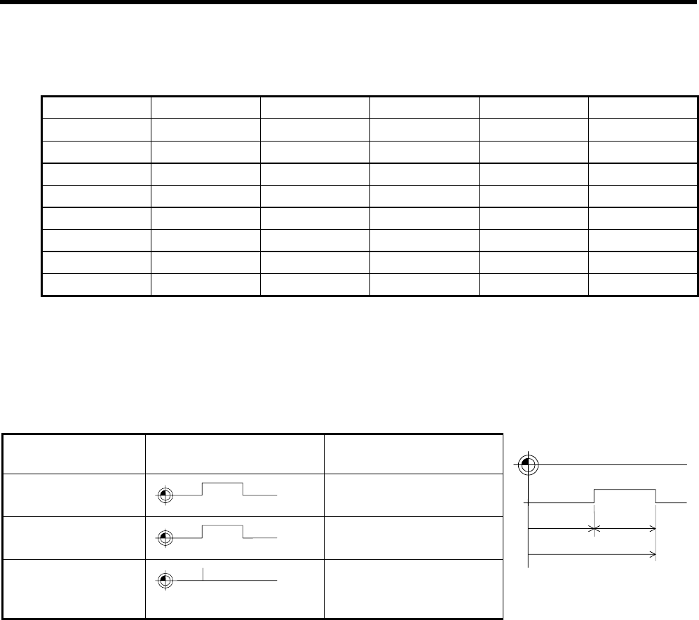
Example of settings of dog1 and dog2 and operation
Setting of dog1 and
dog2
dog1, dog2 position Operation
dog1 < dog2
dog1 dog2
A signal is output between
dog1 and dog2.
dog1 > dog2
dog2 dog1
A signal is output between
dog1 and dog2.
dog1 = dog2
dog1 = dog2
If dog1 equals dog2‚ the
dog1 position triggers a
signal.
dog1
dog2
PSW
width
Imaginary
dog
Basic machine coordinate
system zero point


