© Titan Tool Inc. All rights reserved. 3
Grounding Instructions
This product must be grounded. In the event of an electrical
short circuit, grounding reduces the risk of electric shock by
providing an escape wire for the electric current. This product is
equipped with a cord having a grounding wire with an appropriate
grounding plug. The plug must be plugged into an outlet that
is properly installed and grounded in accordance with all local
codes and ordinances.
WARNING - Improper installation of the
grounding plug can result in a risk of electric
shock.
If repair or replacement of the cord or plug is
necessary, do not connect the green grounding wire to either
at blade terminal. The wire with insulation having a green outer
surface with or without yellow stripes is the grounding wire and
must be connected to the grounding pin.
Check with a qualied electrician or serviceman if the grounding
instructions are not completely understood, or if you are in doubt
as to whether the product is properly grounded. Do not modify
the plug provided. If the plug will not t the outlet, have the
proper outlet installed by a qualied electrician.
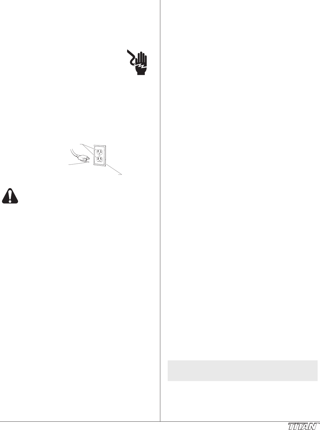
Grounded Outlet
Grounding Pin
Cover for grounded outlet box
Use only a 3-wire extension cord that has a 3-blade
grounding plug and a 3-slot receptacle that will
accept the plug on the product. Make sure your
extension cord is in good condition. When using
an extension cord, be sure to use one heavy
enough to carry the current your product will draw.
An undersized cord will cause a drop in line
voltage resulting in loss of power and overheating.
A 12 gauge cord is recommended. If an extension
cord is to be used outdoors, it must be marked with
the suffix W-A after the cord type designation. For
example, a designation of SJTW-A would indicate
that the cord would be appropriate for outdoor use.
Table of Contents
Specications ........................................................................... 3
General Description ................................................................. 4
Operator Controls ..................................................................... 4
Sprayer Controls ................................................................. 4
Spray Gun Controls ............................................................. 4
Operation ................................................................................... 5
Setup ...................................................................................5
Preparing to Spray .............................................................. 5
Preparing the Spray Material............................................... 6
Spraying .............................................................................. 6
Pressure Relief Procedure .................................................. 6
Spray Gun Operation ............................................................... 6
Using the Spray Gun Controls............................................. 6
Spraying Technique ............................................................ 7
Installing a Texture Nozzle ..................................................7
Converting the Spray Gun from Non-Bleeder to Bleeder ....7
Cleanup ..................................................................................... 8
Maintenance .............................................................................. 8
General Repair and Service Notes...................................... 8
Daily Maintenance ............................................................... 8
Replacing the Diaphragms — PowrTex 300DD ................... 9
Replacing the Diaphragms — PowrTex 600DD ................. 10
Replacing the Reversing Valve ......................................... 11
Troubleshooting ..................................................................... 12
Parts Listings .......................................................................... 14
Main Assembly — PowrTex 300DD ................................... 14
Compressor ....................................................................... 15
Main Assembly — PowrTex 600DD ................................... 16
Electrical Schematic ..........................................................17
Fluid Pump — PowrTex 300DD ......................................... 18
Fluid Pump — PowrTex 600DD ......................................... 19
Motor ................................................................................. 20
PowrTex Gun .................................................................... 21
Texture Nozzle Chart ........................................................ 21
Air Flow Schematic — PowrTex 300DD ................................. 22
Air Flow Schematic — PowrTex 600DD ................................. 23
Accessories ............................................................................ 24
Warranty ..................................................................................24
Specications
PowrTex 300DD and 600DD Sprayers
Gallons per minute (GPM):
PowrTex 300DD ................1.0 (3.8 LPM)
PowrTex 600DD ................3.0 (11.4LPM)
Maximum pressure ........................100 PSI (0.69 MPa)
Compressor Size:
PowrTex 300
DD ................1.5 HP, 8.4 Max. CFM
PowrTex 600DD ................2.0 HP, 11.4 Max. CFM
Voltage .........................................100~120V AC, 50/60 Hz
Maximum current consumption .....15 A
Hopper Size (gallons):
PowrTex 300DD ................12 (45.4 liters)
PowrTex 600DD ................20 (75.7 liters)
Weight:
PowrTex 300DD ................97 lbs. (43.9 kg)
PowrTex 600DD ................122 lbs. (55.3 kg)
Maximum hose length:
PowrTex 300DD ................50’ (15.2 m)
PowrTex 600DD ................100’ (30.5 m)
NOTE: Maximum hose length may vary depending
on the hose diameter and the viscosity of the
material being sprayed.
PowrTex Spray Gun
Maximum Operating Pressure .......100 PSI (0.69 MPa)
Maximum Air Pressure ..................100 PSI (0.69 MPa)
Weight .........................................2.2 lbs. (1 kg)


