0
-,
I
I
'""
_/
UJ
"=:_
/
323
/
/324
-325
/326
/
327
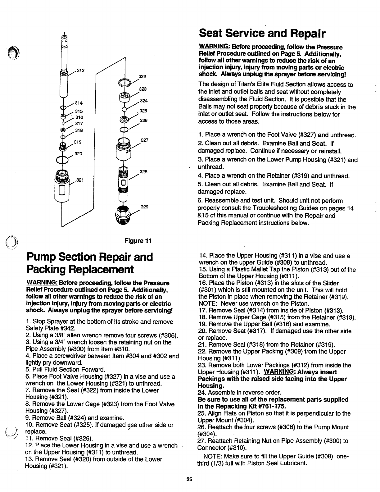
Fig!Jre
11
Pump
Section
Repair
and
Packing
Replacement
WARNING: Before proceeding,
follow
the
Pressure
Relief Procedure
outlined
on
Page 5.
Additionally,
follow
all other
warnings
to
reduce the
risk
of
an
injection injury,
injury
from
moving
parts
or
electric
shock.
Always
unplug
the sprayer before
servicing!
1.
Stop Sprayer at the bottom of its stroke and remove
Safety Plate #342.
2.
Using a 3/8" allen wrench remove four screws (#306).
3. Using a 3/4" wrench loosen the retaining nut on the
Pipe Assembly (#300} from Item
#31
0.
4. Place a screwdriver between Item #304 and #302 and
lightly pry downward.
5. Pull Fluid Section Forward.
6. Place Foot Valve Housing (#327)
in
a vise and use a
wrench on the Lower Housing
(#321) to unthread.
7. Remove the Seal (#322) from inside the Lower
Housing (#321).
8.
Remove the Lower Cage (#323) from the Foot Valve
Housing
(#327).
9.
Remove Ball (#324) and examine.
10. Remove Seat (#325). If damaged use other side
or
/
replace.
11. Remove Seal (#326).
12.
Place the Lower Housing
in
a vise and use a wrench
on the Upper Housing (#311) to unthread.
13. Remove Seal (#320) from outside of the Lower
Housing
(#321
).
25
S~at
Service
and
Repair
WARNING: Before proceeding,
follow
the
Pressure
Relief Procedure
outlined
on Page
5.
Additionally,
follow
all
other
warnings
to
reduce
the
risk
of
an
injection injury,
injury
from
moving
parts
or
electric
shock.
Always
unplug
the
sprayer before
servicing!
The design
of
Titan's Elite Fluid Section allows access to
the inlet and outlet balls and seat without completely
disassembling the Fluid ·Section.
It
is possible that the
Balls may not seat properly because of debris stuck in the
inlet or outlet seat. Follow the instructions below
for
access to those areas.
1. Place a wrench on the Foot Valve (#327)
and
unthread.
2. Clean out all debris. Examine Ball and Seat. If
damaged replace. Continue if necessary
or
reinstall.
3. Place a wrench on the Lower Pump Housing (#321) and
unthread.
-
4. Place a wrench on the Retainer (#319)
and
unthread.
5.
Clean out all debris. Examine Ball and Seat. If
damaged replace.
6. Reassemble and test unit. Should unit
not
perform
properly consult the Troubleshooting Guides on pages 14
& 15 of this manual
or
continue with the Repair and
Packing Replacement instructions below.
14. Place the Upper Housing (#311)
in
a vise and use a
wrench on the upper Guide (#308) to unthread.
15. Using a Plastic Mallet Tap the Piston (#313) out of the
Bottom
of
the Upper Housing (#311).
16.
Place the Piston (#313)
in
the slots of the Slider
(#301) which is still mounted on the unit. This will hold
the Piston in place when removing the Retainer (#319).
NOTE: Never use wrench
on
the Piston.
17. Remove Seal (#314) from inside of Piston (#313).
18.
Remove Upper Cage (#315) from the Retainer (#319).
19.
Remove the Upper Ball
(#316}
and examine.
20. Remove Seat (#317). If damaged use the other side
or
replace.
21. Remove Seal (#318} from the Retainer (#319).
22. Remove the Upper Packing (#309) from the Upper
Housing
(#311
).
23. Remove both Lower Packings (#312} from inside the
Upper Housing (#311). WARNING:
Always
insert
Packings
with
the
raised
side
facing
into
the
Upper
Housing.
24. Assemble
in
reverse order.
Be
sure
to
use
all
of
the
replacement
parts
supplied
in
the
Repacking
Kit
#761-175.
25.
Align Flats
on
Piston so that it is perpendicular to the
Upper Mount (#304). ,
26. Reattach the four screws (#306) to the Pump Mount
(#304). .
27.
Reattach Retaining Nut
on
Pipe Assembly (#300) to
Connector (#310).
NOTE: Make sure to fill the Upper Guide (#308) one-
third
(1/3) full with Piston Seal Lubricant.


