Rev. E
Reelmaster 6500-D/6700-DHydraulic System Page 4 - 78
3. Make sure manifold is clean before removing the
cartridge valve. Remove the valve and seal kit.
4. Visuallyinspect themanifold portand cartridgevalve
for damage to sealing surfaces, damaged threads, and
contamination.
A. Contamination may cause valvesto s tick or hang
up, it can become lodged in small v alve orifices or
seal areas causing malfunction.
B. If sealing surfaces appearpitted or damaged, the
hydraulic system may be overheating or there may
be water in the system.
CAUTION
Use eye protection such as goggles when using
compressed air.
5. If necessary, clean cartridge valve using clean min-
eral spirits. Submerge valve in clean mineral spirits to
flushoutcontamination. Particlesas fineas talcumpow-
der can affect the operation of high pressure hydraulic
valves. Clean and dry with compressed air.
6. Reinstall the rotary cartridge valve:
Note: Mow manifold(Fig. 45) usestwo typesof manu-
al rotary cartridge valves: flow control (reel speed -- size
10) and 4--way directional control (backlap -- size 12).
Installation torque values are different for each type.
A. Lubricate new O-ring and backup ring of seal kit
with clean hydraulic oil and install. The O-ring and
backup ring of s eal kit must be arranged properly on
the cartridge valve for proper operation and sealing.
B. Thread valve carefully into the port. The valve
should go in easily without binding. Torque valve to
specification shown in manifold illustration.
7. Install knob assembly (reel manifold shown in Fig.
45):
A. Install locating plate so that the pin seats into the
locating hole.
B. Turn the threaded cartridge valve stem carefully
clockwise until it stops.
C. Face detent platecounterbore down. Thread det-
ent plate down onto the valve stem until it is stopped
by the locating plate. Turndetent plate backcounter-
clockwise 1/4 turn.
D. Center one detentplate hole overa locatingplate
indentation. Drop a ball into each hole, then drop a
spring into each hole.
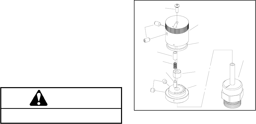
1. Handle Base
2. Handle Cap
3. Detent Pin
4. Compression Spring
5. Bushing
6. Set Screw (2 used)
7. Set Screw (2 used)
8. Screw
9. Lip Seal
10. Sleeve Bearing
11. Flow Control Valve
Figure 48
6
5
4
7
9
10
3
2
8
1
11
E. On the 2-position directional valve cartridge,
placeindicatorplateoverthe detentplate.Makesure
thearrow points directly at thenumber 1 on thelocat-
ing plate.
F. Onflowcontrolcartridgevalvecartridge,placein-
dicator plate over the detent plate. Make sure the ar-
row points to the right at 45_.
G. While pushing down on the indicator plate and
compressing the springs, thread down a jam nut.
While tightening the set screw, tighten jam nut at the
same time using a 7/16 - inch wrench.
H. Threadsecond jamnutalltheway downthevalve
stem. Apply ”Loctite 242” or equivalent the valve
stem threads. Screw knob all the way down until it
hits the upper jam nut.
I. On 2-position directional cartridge valve car-
tridge, turn knob counterclockwise so the arrow is
90_ with the back of the manifold. Simultaneously
tighten upper jam nut and turn knob so it is tight and
the arrow is pointing 45_ to the right in line with the
indicator plate.
J. On flow control valve cartridge, turn knob coun-
terclockwise until the arrow points at the number ”5”.
Simultaneously tighten upper jam nut and turn knob
so it is tight and the arrow is pointing at the number
”1” on the locating plate.


