


C307 and C308 with R333 and R335 provide the
compensation necessary to ensure stability when the loop is
closed. They are Miller capacitors which dramatically reduce
the transimpedance (i.e. current to voltage gain) of the current
mirrors at high frequencies. The present value of 47pF
provides for a unity gain open loop bandwidth of around
75MHz, whilst ensuring a closed loop gain margin of around
6dB (note that gain margin in a current feedback design is not
dependent on system bandwidth to a first order
approximation). R333 and R335 provide a ‘zero’ in the open
loop frequency response which is tailored to give the best
time domain performance (i.e. to make high frequency square
waves look square with minimal ringing or overshoot).
DZ304 and C311 provide a fixed 4.7V bias voltage to allow
the following stages to operate correctly. C311 is there to
ensure that both halves of the following stage receive an
equal AC signal component at high frequency.
TR310 and TR307 are the ‘pre-driver’ transistors, which act
to buffer the outputs from the preceding stage and drive the
Darlington output power transistors. TR309 and R321 act as a
current limit, to ensure that the emitter current of TR310 does
not exceed 30mA in a fault condition. TR306 and R323
provide the same function for TR307.
R338 and R339 are to loosely couple the outputs of the pre-
driver stage to the inputs of the Darlington power output
devices. This is so that the inbuilt temperature sensing diodes
of the output transistors can accurately control the quiescent
current of the output stage as the junction temperature of the
power devices varies. C312 and C318 ensure that both halves
of the output stage receive an equal AC signal component.
The output transistors are TR318 and TR319. These are
Sanken SAP15N and SAP15P devices respectively. They are
specially designed for audio power amplifier use. In addition
to high current gain (Darlington with a typical
hFE
of 20,000)
they provide an inbuilt emitter resistor (thick film power
resistor of 0W22) and temperature sensing diodes which
closely and rapidly track the
VBE
versus temperature
characteristic of the power transistors, allowing for easy, fast-
responding and reasonably accurate control of quiescent
current.
RV300 is for fine trimming of the quiescent current. PL300
provides a convenient measuring point for this, which is
short-circuit protected in the event of a slip with the
multimeter probe! All of the remaining circuitry to the right
of TR318 and TR319 is essentially for output stage
protection...
Transistors TR312 and TR304, along with the network of
resistors and capacitors to which they are connected, provide
instantaneous overload protection of the output stage. This is
a conventional single slope VI protection scheme, which
allows much greater current to be delivered into a rated load
than into a short circuit. The values allow for 18A peak
delivery (at clip) into a purely resistive load, 7A peak (at clip)
into a purely capacitive load and around 4A peak into a short
circuit. R345, C303, R346 and C304 allow these values to be
doubled for short transient bursts (approximately 2.7
milliseconds) so that impulsive musical transients can be
delivered cleanly with minimal risk of damaging the output
transistors.
TR313, TR302 and their associated components send a signal
to the microprocessor when the instantaneous protection
circuits are having to work ‘hard’ to prevent amplifier
overload. This instructs the micro that the user is severely
abusing the amplifier and will switch off the loudspeaker
relays to prevent possible permanent damage. In reality, if
you short circuit the outputs at any appreciable volume level,
this circuit will trigger and the microprocessor will turn off
the loudspeaker relays and send a signal to the user.
R308, R314 and C320 form a low pass filter from which
the DC detection circuits can sense excessive DC at the
loudspeaker outputs. If there is any positive DC present,
then TR316 will turn on, which turns on TR305 and thus
activates the DC protection line to the micro, turning off
the loudspeaker relays.
If there is any negative DC present, then TR308 will turn
on, which turns on TR317 which then turns on TR305 in
turn, causing the same effect.
R350 and C319 are the Zobel network which is provided
to ensure the amplifier ‘sees’ a constant and resistive load
at very high frequencies, to aid stability, although the
amplifier will be stable without the Zobel fitted.
C313 locally couples the ‘high frequency’ and loudspeaker
ground returns together at the output to overcome the
effects of track inductance back to the star point. C309
couples the ‘high frequency’ and signal grounds together
at the input for the same reason.
D303 and D304 are ‘flyback’ diodes to protect the output
transistors from reverse bias when the amplifier is heavily
clipped into an inductive load (such as a loudspeaker voice
coil!)
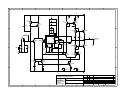
Sheet 4 is an identical copy of sheet 3 so I will not
describe it separately.