


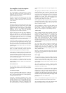
Pre-amplifier circuit description
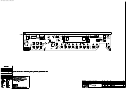
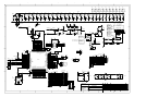
Refer to L937 circuit diagrams
The A32 preamplifier is a high-performance, DC coupled
design with microprocessor control of input select, two
independent tape loops, electronic volume control, tone
bypass and electronic tone control.
It features a discrete power supply and low-noise linear
circuitry to obtain very good distortion and noise
performance, suitable for high quality source material such
as CD or DVD-A.
Input switching
Each of the inputs has a pair of diodes to the ±15V rails to
prevent static spikes from causing damage to the CMOS
multiplexers. In addition, there is a simple resistor-
capacitor filter with a corner frequency of approximately
340kHz to remove any unwanted high frequency
interference from the signal. This uses high-quality
polypropylene capacitors for best performance.
Z104 and Z105 are the main input select multiplexers,
which are configured in a ‘virtual earth’ unity gain
arrangement with Z115 and Z116. This arrangement is
slightly lower distortion than the ‘normal’ one, at the cost
of a slightly higher noise floor. It is an inverting
configuration, which is restored to correct polarity by the
inverting electronic volume control which follows.
Z115B and Z116B are integrating servos, which take out
any DC from the input signal before the following stages.
The servos are 2-pole, with a passive 2
nd
pole being
formed by R180 and C147 (for the left channel) to remove
broadband noise from the output of the servo and improve
speed of response.
Z100 thru Z103 are the input selectors for the 2 tape loops.
These are normal non-inverting selectors which are
buffered before being passed on to the phono sockets.
Z109A output is decoupled by R108 which is included in
the feedback path. Local high frequency feedback occurs
around C108 to allow the tape loop output to be very low
impedance, whilst being stable into a capacitive load such
as may be presented by a screened interconnect cable. This
is the same for all tape outputs.
Z106 is configured as a double pole changeover switch,
used to select the tone controls. The tone controls are
bypassed when not required so that the noise and distortion
can be minimised.
Tone control circuit
The tone control circuit is a non-inverting one, using a
gyrated ‘bell’ filter for the bass and a simple shelving filter
for the treble.
Left channel description
The input is attenuated by 6dB and biased to a voltage of
+2.5V DC by C111, R113, R112, R110, R111 and C110.
This is so the signals fall within the 0 - 5VDC required by
the digital potentiometer Z108.
Z111B and its associated components form an active
equivalent of a series resonant LCR circuit. This has an
impedance minimum of 5.4k˜ at around 80Hz with Q=0.7
The reason the bass is done as a band-boost filter rather
than a shelving filter is so that you can boost the ‘real’
bass without causing lots of sub-audio loudspeaker cone
excursion which wastes power and may damage the drive
units.
The digital pots Z108D and Z108A control the bass and
treble respectively. This is done by moving the wiper
connected to the frequency-sensitive impedance between the
non-inverting and inverting terminals of Z112A, effectively
changing the ratio of feedback boost and feed-forward
attenuation of the circuit at the desired frequencies, thus
providing a EQ gain control that is symmetrical on a
logarithmic scale, with the use of a linear pot.
Z112B provides the 6dB of gain necessary to bring the
nominal signal level back to unity. C116 and C117 remove
the 2.5VDC offset from the output, to prevent clunks when
the tone controls are activated.
Z108 is controlled by a simple 3-wire serial interface from
the microprocessor. Each of the digital lines has its own
ground return to minimise electromagnetic interference.
They are connected together only at the GND pin of the IC.
Volume control
Z107 is a VSDVC electronic volume control IC. It works, in
conjunction with an external op-amp, by varying the feed-
forward and feedback resistors in an inverting gain
configuration. In this way, it can allow output signal swings
of up to 22Vpp whilst operating from a single +5VDC power
supply. Also, it allows the user the choice of external
circuitry to fine-tune the performance. The gain is controlled
from the microprocessor via a 3-wire serial interface. The
analogue supply rail is derived from the local +5V via R185
and C156 // C157.
Z117 is the output op-amp. Its outputs are decoupled via
R186, R187, C158 and C159 so that it has a low output
impedance but can drive cable capacitance without
oscillation. R186 and R187 are included in the audio
frequency feedback loop to reduce output impedance when
driving ‘difficult’ cables.
RLY100 is a mute relay which shunts the preamp output to
ground. This is to prevent thumps and squeals when the units
is powered up or down.
Power supply
The transformer winding is connected to SK300. The voltage
is rectified and smoothed by D300, D301, D306, D307 and
C300, C310. The unregulated voltage should be around
±27VDC. F300 and F301 are secondary fuses, as the low
power preamp winding would not blow the primary fuses if
short circuited.
The voltage regulators are discrete compound emitter
followers. I will describe the +15V supply as the negative is
essentially an exact mirror image.
Q300 and R300 act as a constant current source, supplying
around 7mA into D310. C302 and C314 reduce ripple and
broadband noise on the zener diode. Q305 and Q306 form a
complementary Darlington NPN transistor which is
configured as an emitter follower, producing the +15VDC at
its output. C303 is to provide bulk charge storage and to
reduce the AC output impedance of the power supply. D302
prevents reverse bias of the supply during
power down.
Z301 is a conventional LM317 type circuit to drop the +15V
rail down to +5V for the tone and volume control circuits.
Star point SP300 explicitly connects the differently named
ground nets together at one point, to minimise hum.