


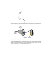

Align the mounting holes in the bottom half of the crossover unit with the holes you have drilled at the
installation site. Pass the four #6 x 1 1/4" screws through the holes in the crossover unit, and tighten them
until the assembly is firmly in place. As before, do not over-tighten; this is especially important if the
mounting surface is not perfectly flat.
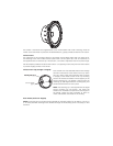
After all the connections and any necessary adjustments have been made snap the cover back in place.
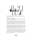
connecting the system
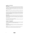
Trim the speaker wire as needed. Strip about 1/4" (6 mm) of the insulation from the ends. Twist the
exposed strands thoroughly to prevent any loose strands from causing a short circuit. You may also "tin"
the wire with a soldering iron. The wires attach to a removable connector which in its assembled position
has the screws facing the bottom of the crossover. Insert the prepared wire into the appropriate location
(see diagram or refer to the crossover circuit board) in the connector strip and tighten the screws to secure
the wires in place. Be sure to note the polarity marking on the circuit board.
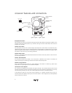
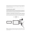
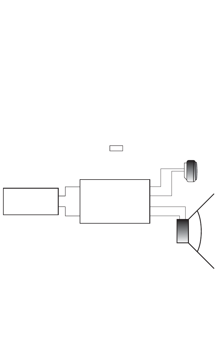
crossover connections and input switch setting
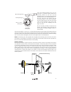
Route the wires connected to the input terminals on the crossover network to the power amplifier.
Connect the wires to the amplifier outputs as recommended by the manufacturer of the unit. Make sure
there are no stray strands of wire which could cause a short circuit. Observe left/right polarity markings.
NOTE: In this configuration, you may connect the amplifier (+) positive to either the tweeter (+) or woofer
(+) terminal, and the amplifier (-) negative to either the tweeter (-) or woofer (-) terminal. The parallel
switch ensures that both halves of the crossover are supplied with signal as least one (+) and (-) input
terminal are connected.
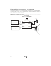
Tweeter
Woofer
Amplifer
Crossover
IN OUT
+
-
-
+
-
+
-
+
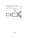
Woofer
Tweeter
Woofer
Tweeter
+
-
+
-
+
-
Standard
(Switch in Parallel Position)