


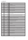
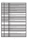
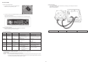

Pin No. Pin Name I/O Description
1 DEFI I Defect detection signal (DEF) input. (Must be connected to 0V when unused.)
2 TAI I For PLL/Test input. A pull-down resistor is built-in. (Must be connected to 0V.)
3 PDO O External VCO control phase comparator output.
4 VVSS - Intetnal VCO ground. (Must be connected to 0V.)
5 ISET I PDO output current adjustment resistor connection.
6 VVDD - Internal VCO power supply.
7 FR I VCO frequency range adjustment.
8 VSS - Digital system ground. (Must be connected to 0V.)
9 EFMO O Slice level control EFM signal output.
10 EFMIN I Slice level control EFM signal input.
11 TEST2 I Test input. A pull-down resistor is built-in. (Must be connected to 0V.)
12 CLV+
O
Disc motor control output. Can be set to three-value output by microprocessor
13 CLV- command.
14 V/P O
Rough servo/phase control automatic switching monitor output. Outputs a high level
during rough servo a low level.
15 HFL I Track detection signal input. This is a Schmitt input.
16 TES I Tracking error signal input. This is a Schmitt input.
17 TOFF O Tracking off output.
18 TGL O Tracking gain switching output. Increase the gain when low.
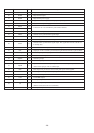
19 JP+
O
Track jump output. Three value output is also possible when specified by0
20 JP- microprocessor command.
21 PCK O EFM data playback clock monitor. Output 4.3218 MHz when the phase is locked.
Synchronization signal detection output. Output a high level when the synchronization
22 FSEQ O signal detected from the EFM signal and the internaly generated synchronization signal
range.
23 VDD - Digital system power supply.
24 ~ 28 CONT1 ~ 5 I/O General purpose input/ output pin1 ~ 5.
29 EMPH/CONT6 O
De-emphasis monitor. A high level indicates playback of a De-emphasis disk./ General
General purpose input/ output pin6.
30 C2F O C2 flag output.
31 DOUT O Digital output.
32 TEST3 I Test input. A pull-down resistor is built-in. (Must be connected to 0V.)
33 TEST4 I Test input. A pull-down resistor is built-in. (Must be connected to 0V.)
General purpose input/ output command identifying. A pull-down resistor is built-in.
34 PCCL I "H": Control possible only for the general purpose input/ output port command.
"L": Control possible for all commands.
35 MUTEL/CONT7 O Left channel mute output./ General purpose input/ output pin.
36 LVDD - Left channel power supply.
37 LCHO O Left channel output.
38 LVSS - Left channel groud. (Must be connected to 0V.)
IC, LC78622NE
- 27 -