


33..33..22 MMoouunnttiinngg AAnntteennnnaass oonn FFlloooorr
SSttaannddss
33..33..33 WWaallll//CCeeiilliinngg MMoouunnttiinngg
33..44 CCoonnnneeccttiinngg AAnntteennnnaass
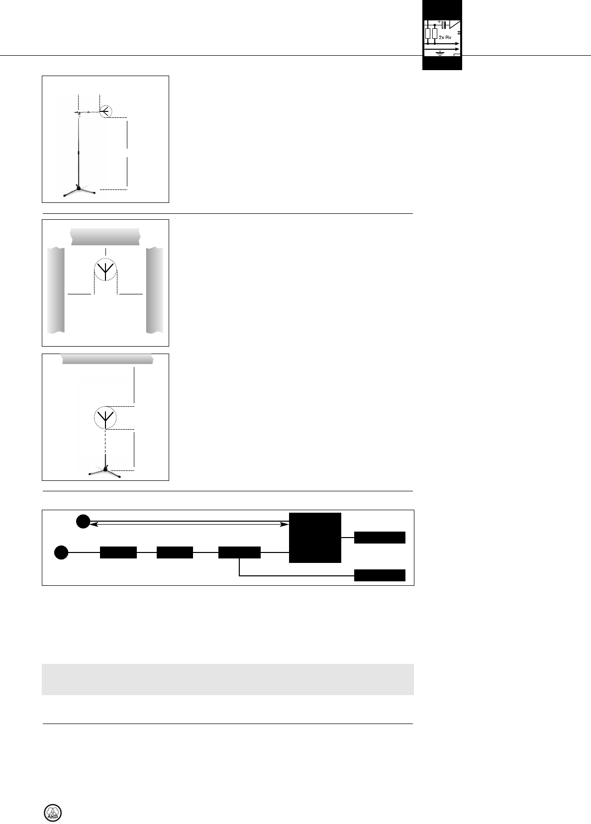
33..44..11 SSiinnggllee--cchhaannnneell SSyysstteemm
wwiitthh PPaassssiivvee AAnntteennnnaass
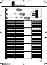
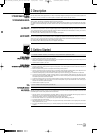
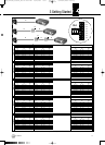
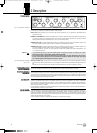
Refer to Table 1 on page 17
and fig. 6.
Fig. 6: Wiring a single-channel system with
passive antennas and different antenna
cable runs.
Refer to fig. 6.
IImmppoorrttaanntt!!
33..44..22 SSiinnggllee--cchhaannnneell SSyysstteemm
wwiitthh AAccttiivvee AAnntteennnnaass
Refer to Table 1 on page 17
and fig. 7 on page 16.
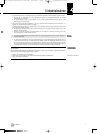
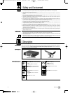
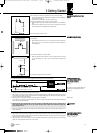
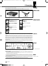
When mounting the antennas on floor stands, be sure to proceed as follows:
1. Use the supplied SA 63 or the integrated stand adapter to mount the antenna on
the boom of a boom stand.
2. Pull the boom out all the way to one side to make sure the
antenna will be at least 28 inches (70 cm) away from the stand.
3. Extend the stand high enough to place the boom at least 6 ft. (1.8 m) above the
floor.
4. Wind the antenna cable around the boom. Do not allow the cable to sag below
the boom because this may degrade the reception quality.
Fig. 3: Antenna mounted on floor stand
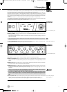
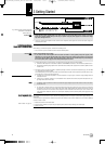
If you mount your antennas on a wall or ceiling, be sure to keep the following mini-
mum distances:
1. Mount the antenna at least 10 cm (4 in.) in front of and at a minimum lateral dis-
tance of 50 cm (20 in.) from any walls or other plane surfaces, metal grids, or
metal scaffolding.
Fig. 4: Minimum distances from plane surfaces.
2. Make sure the antenna will sit at least 15 cm (6 in.) above the floor or 50 cm (20
in.) from the ceiling (or 15 cm (6 in.) if you route the cable to the antenna from
above).
Fig. 5: Minimum distances from floor and ceiling.
For a single-channel system, you need no antenna splitter. Connect the antennas to the receiver directly.
1. Measure the cable run between the receiver and each antenna.
2. Refer to Table 1 on page 17 to find out whether you will need to break the cable run down into several cables and insert one or
two AB 4000 antenna boosters. Table 1 states the maximum acceptable cable lengths for RG58 and RG213 cables separately.
3. Connect an antenna cable to each antenna.
4. Referring to Table 1, connect the antennas to the antenna inputs on the receiver.
If you need one or two AB 4000 antenna boosters, you will need to insert an ASU 4000 remote power adapter between the
receiver and the first antenna booster.
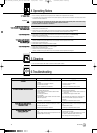
5. Check that the AC mains voltage stated on the power supplies for the ASU 4000 and the receiver is identical to the AC
mains voltage available where you will use your system. Using the power supplies with a different AC voltage may
cause damage to the unit.
6. Connect the remote power adapter and the receiver to their respective power supplies and connect each power supply to a con-
venient power outlet.
1. Measure the cable run between the receiver and each active antenna.
2. Refer to Table 1 on page 17 to find out whether you will need to break the cable run down into several cables and insert one or
two AR 4000 antenna boosters. Table 1 states the maximum acceptable cable lengths for RG58 and RG213 cables separately.
3. Connect an antenna cable to each antenna.
4. Referring to Table 1, connect each antenna to one or two AB 4000 antenna boosters (if necessary), an ASU 4000 remote power
adapter, and to the appropriate antenna input on the receiver.
3 Getting Started
PS 4000 W 15
˛
˛
≥ 10cm
˛
˛
˛
˛
≥
50cm≥50cm
˛
≥ 70cm
˛
˛
≥ 180cm
˛
RG58: 0 - 13 m / RG213: 5 - 26 m
AA::
RG58: 0 - 13 m / RG213: 5 - 26 m
BB::
RG58: 6 - 46 m / RG213: 12 - 97 m
Antenna
Antenna
AABB 44000000
AASSUU 44000000
<<-- DDCC//AACC -->>
AABB 44000000
<<-- DDCC//AACC -->>
RReecceeiivveerr
AA BB BB
▲
!
˛
˛
≥ 15cm
˛
˛
≥ 50 (15) cm
BDA_PS4000W_D030928_neu:PS 4000-Hex 01/20/2010 18:17 Seite 15 (Schwarz/Black Auszug)