


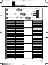
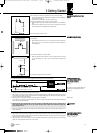
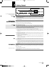
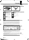
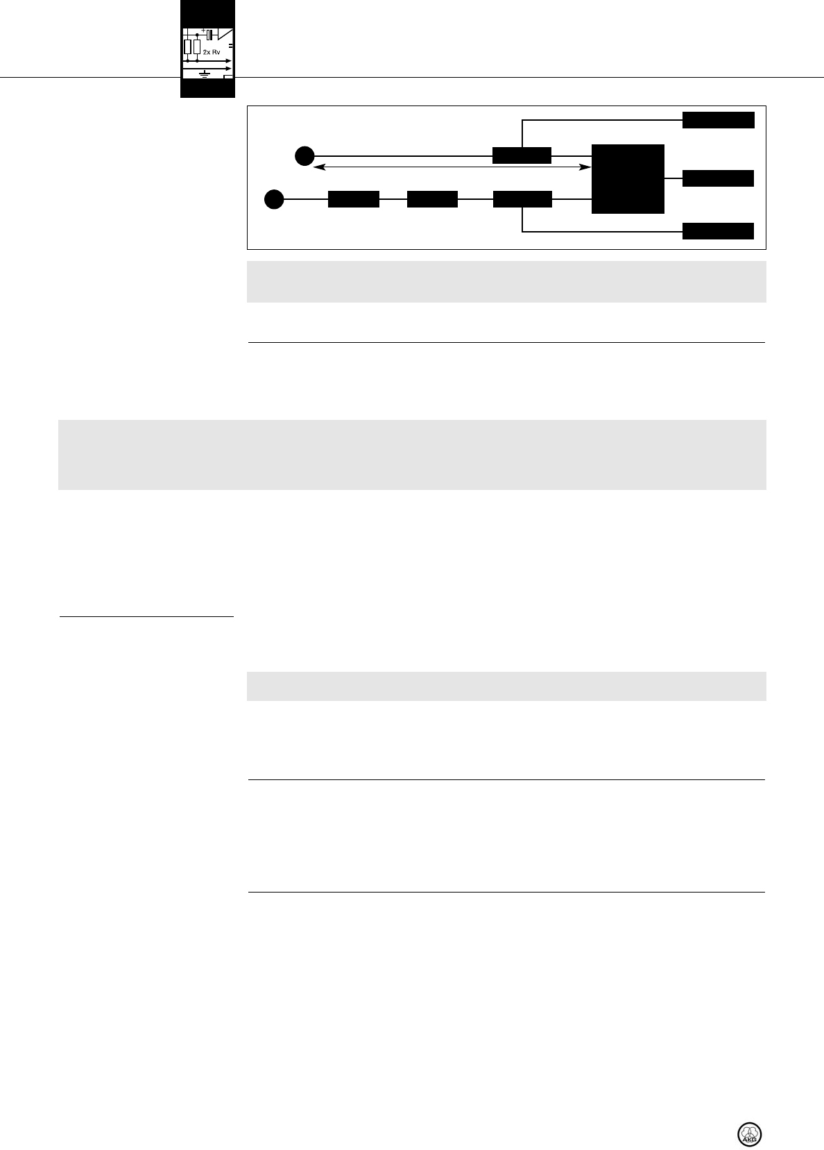
Fig. 7: Wiring a single-channel system with
active antennas and different
antenna cable runs.
Important!
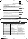
33..55 MMuullttiicchhaannnneell SSyysstteemmss
wwiitthh PPSS 44000000 WW AAnntteennnnaa SSpplliitttteerrss
Warning!
NNoottee::
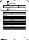
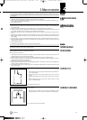
33..66 TThhee CCLLAA SSwwiittcchh BBaannkk
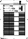
Refer to Table 1 on page 17.
5. Check that the AC mains voltage stated on the power supplies for the two ASU 4000s and the receiver is identical to
the AC mains voltage available where you will use your system. Using the power supplies with a different AC voltage
may cause damage to the unit.
6. Connect the remote power adapters and the receiver to their respective power supplies and connect each power supply to a
convenient power outlet.
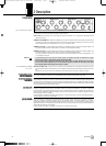
For wiring examples for multichannel systems, refer to figs. 10 through 13 on page 56.
When setting up a multichannel system, remember the following points:
1. You can connect up to four receivers to each PS 4000 W antenna splitter.
Systems with distributed power supplies
• If you power both the antenna splitter and the receivers connected to it from (optional) local power supplies, make
absolutely sure to connect the antenna splitter power supply and the power supplies of the receivers to a common AC
power circuit with an ON/OFF switch. Failing to switch power to all devices on simultaneously may cause damage to
the antenna splitter power supply due to the load presented by the receivers.
2. For large systems with up to 50 channels you can daisy-chain the required number of antenna splitters:
• Connect the LINK outputs on the first antenna splitter to the ANTENNA IN connectors on the next antenna splitter and so on.
• We recommend powering large systems from optional PSU 4000 central power supplies for three antenna splitters and four
receivers each.
3. Each antenna input on the antenna splitter is capable of powering a maximum of three active components (e.g., RA 4000 B/W
+ 2 x AB 4000) via the antenna cables.
In the following cases you will need an ASU 4000 remote power adapter to power active components (each ASU 4000 is capa-
ble of powering up to three active components, too):
• The cable run from the antenna splitter to an active component is long enough to reduce the supply voltage below the
acceptable minimum.
• A device (e.g., an antenna combiner*) in the line between the PS 4000 W and an active component interrupts the DC sup-
ply voltage across the antenna cable.
* The ZAPD 21 antenna combiner from Mini Circuit feeds the supply voltage through. Similar devices from other manufactur-
ers may not do so.
• You have used an antenna combiner to connect two antenna lines to the same antenna input. If you use three or more active
components in one antenna line, insert an ASU 4000 remote power adapter between the antenna combiner and the first of
the active components. If the number of active components in both lines totals more than three, be sure to insert an ASU
4000 remote power adapter into each line. The remote power adapter prevents the antenna splitter power supply from being
overloaded.
The RF signal level at each antenna input on the antenna splitter(s) depends on the frequency band, antenna type, cable type, and
cable length.
To ensure optimum signal level at the antenna input, set the CLA switches on each antenna booster and on the antenna splitter(s)
as shown in Table 1 below.
1. Remove the cover of the CLA switch bank.
2. Set the three DIP switches as required for your frequency band, antenna model, cable type, and cable length.
3. Replace the cover.
3 Getting Started
16
PS 4000 W
S
RA 2 B/W
SRA 2 B/W
AABB 44000000 AASSUU 44000000
AASSUU 44000000
<<-- DDCC//AACC -->>
<<-- DDCC//AACC -->>
AABB 44000000
<<-- DDCC//AACC -->>
RReecceeiivveerr
RG58: 0 - 13 m / RG213: 5 - 26 m
AA::
RG58: 0 - 13 m / RG213: 5 - 26 m
BB::
RG58: 6 - 46 m / RG213: 12 - 97 m
AA BB BB
▲
!
▲
!
BDA_PS4000W_D030928_neu:PS 4000-Hex 01/20/2010 18:17 Seite 16 (Schwarz/Black Auszug)