


14-EN
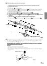
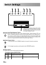
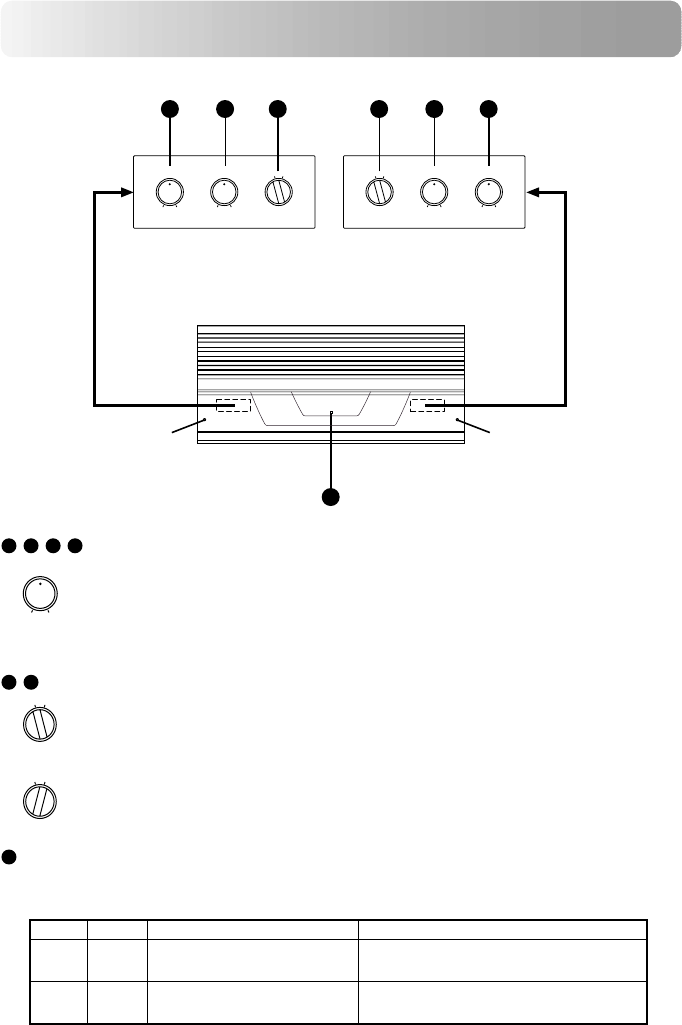
Switch Settings
7
,
8
,
11
,
12
Input Gain Adjustment Control
Set the MRV-F900 input gain to the minimum position. Using a dynamic CD as a
source, increase the head unit volume until the output distorts. Then, reduce the vol-
ume 1 step (or until the output is no longer distorted). Now, increase the amplifier gain
until the sound from the speakers becomes distorted. Reduce the gain slightly so the
sound is no longer distorted to achieve the optimum gain setting.
9
,
10
Mode Selector Switch
1) Set this switch to the “NORMAL” position for normal 4-channel connections.
2) For bridged connections, set the switch to the “BRIDGED” position.
13
Status indicator
Amplifier status can be confirmed with the indicator.
Blue
Light
• Protection indicator (PROTECTION)
Red
Light
Condition
Amplifier circuit is normal.
Amplifier circuit is abnormal.
Solution
Contact your authorized Alpine dealer.
7
8 9 10 11 12
13
★★
CH-2
GAIN MODE
NOM(1.0V)
MAXMIN
BRIDGEDNORMAL
CH-1
GAIN
NOM(1.0V)
MAXMIN
CH-3
GAINMODE
NOM(1.0V)
MAXMIN
BRIDGEDNORMAL
CH-4
GAIN
NOM(1.0V)
MAXMIN
GAIN
NOM(1.0V)
MAXMIN
MODE
BRIDGEDNORMAL
MODE
BRIDGEDNORMAL
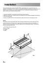
★ Take off the two hexagon screws when switch
setting and open the door. When you finish
the switch setting, close the door and fix with
the original hexagon screws.