


SVP-1500 Bass Amplifier
4
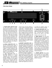
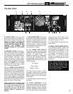
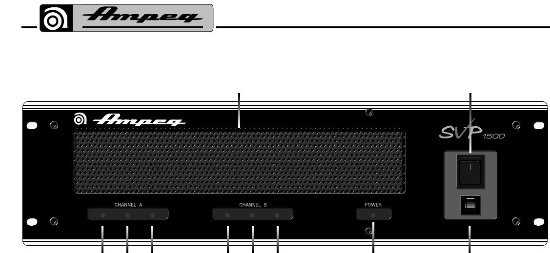
The Front Panel
SIGNAL LIMIT PROTECT SIGNAL LIMIT PROTECT RESET
2 3 4 2 3 4 6
71
5
10
A
M
P
1: FRONT PANEL EXHAUST VENT:
The SVP-1500 employs a variable-
speed internal cooling fan to draw air
through the unit to keep it running cool
even under extreme operating condi-
tions. The air is drawn in through the
unit's rear intake vent (#11) and is
forced out through the front panel
exhaust vent. This method of cooling
draws air out from the interior of the
rack and provides more efficient cool-
ing than methods which bring air in
from the front and exhaust it through
the back. Keep this vent clear and
free from obstruction at all times to
insure proper cooling.
2: SIGNAL INDICATOR LED: This
LED will illuminate when signal is
detected at the amplifier's output ter-
minals, providing accurate visual con-
firmation of signal presence, often
helpful in hookup and troubleshooting.
The level of the signal must be at
about 5% of the amplifier's full rated
output to make the LED glow.
3: LIMIT INDICATOR LED: The
SVP-1500 employs an internal
"Automatic" limit circuit to prevent
amplifier "clipping". The Limit LED will
illuminate whenever the input signal
attempts to overdrive the amplifier's
output section, indicating that the
Limiter has been called upon to pre-
vent clipping. (Not only does clipping
produce harsh sounding distortion, it
is also capable of damaging speaker
components - particularly high fre-
quency drivers.) Periodic flashing of
the Limit LED indicates operation at or
near full output and is no cause for
alarm. Steady illumination of the LED
indicates constant operation of the
Limiter, with the possibility that the
input signal should be reduced by
means of the Sensitivity control (#13).
The Limiter within the SVP-1500 is
fully automatic, with no defeat switch,
insuring complete protection against
clipping at all times.
4: PROTECT INDICATOR LED: This
LED will illuminate whenever the inter-
nal protection relay on either channel is
activated, indicating the possibility of
overheating, DC voltage at the outputs,
overloads or short circuits. The protec-
tion relay is activated for a short period
upon initial turn-on and at turn-off to
prevent transient "spikes" from being
reproduced through your speakers. If
the limit and protect indicators for a
channel cycle on and off with a signal
applied, this indicates the presence of
a short circuit or load impedance less
than 2 ohms on the output of that chan-
nel (less than 4 ohms in the bridged
mono mode). In this case, check all
wiring for shorts, check the total con-
nected load impedance to be sure it is
not below the amplifier ratings, or
check for other potential problems.
5: POWER INDICATOR LED: This
LED will illuminate when AC power is
applied by means of the Power switch
(#7). If the LED fails to illuminate,
check the AC outlet or the circuit
breaker on the front panel (#6).
6: RESET SWITCH: The SVP-1500
employs an AC line circuit breaker to
help protect against damages due to
excessive current demands. If the
amplifier does not function, check the
circuit breaker. If it has opened, the
button will be protruding and showing
a contrasting color. You may reset it
by pressing the button in until it latch-
es. The circuit breaker must cool
down for a short time before the but-
ton will latch. If the circuit breaker
opens repeatedly with no signal input,
have the amplifier checked by a qual-
ified service person.
7: POWER SWITCH: This switch
turns the amplifier On in the Up posi-
tion and Off in the down position.
When AC power is applied to the
amplifier, the Power LED indicator
(#5) will illuminate.