


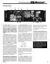

8: POWER CORD: This heavy duty
power cord must be connected to a
grounded AC outlet of the proper volt-
age for the amplifier to operate. IN
ORDER TO AVOID THE POSSIBILI-
TY OF ELECTRIC SHOCK, DO NOT
REMOVE OR BYPASS THE
GROUND PRONG OF THE POWER
CORD.
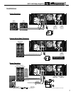
9: SPEAKON
®
JACKS: These heavy-
duty output jacks offer an excellent
method of connecting the amplifier to
your speakers using cables terminat-
ed with Speakon
®
type plugs. Use of
these connectors is highly recom-
mended under high power operation.
When using the amplifier in the Mono
Mode, you MUST use the middle
Speakon
®
jack. Please refer to pages
6 and 7 for more information.
10: 1/4" PHONE JACK OUTPUTS:
These additional output jacks offer an
alternative method of connecting to
your speakers, using cables terminat-
ed with 1/4" phone plugs. Since these
jacks are not as well suited to high
current applications as the Speakon
®
jacks, they are NOT recommended for
extended use at high power levels, or
when driving 2 or 4 ohm loads.
NOTE: In some areas 1/4” jacks are not
acceptable for use on amplifiers capa-
ble of high output power levels. For
this reason the 1/4” jacks on your
amplifier may be sealed – use ONLY the
Speakon
®
jacks for connecting your
speakers.
11: FAN INTAKE AREA: The internal
cooling fan is mounted directly behind
this cover, drawing cooling air into the
amplifier to help prevent it from run-
ning hot. This area must be kept free
from obstruction! Check the Intake
Area periodically and remove any for-
eign materials if needed.
12: 1/4" PHONE JACK INPUTS:
These jacks accept line level signal
sources by means of cables fitted with
standard 1/4" phone plugs. Low
impedance balanced or unbalanced,
as well as high impedance sources,
are acceptable for these inputs. Low
impedance balanced inputs are to be
wired as follows:
Tip: Signal +
Ring: Signal -
Sleeve: Ground
The input channel circuitry is trans-
formerless electronically balanced,
and requires a line level signal of 1.5V
RMS or greater to drive the amplifier
to full output.
In the Mono Mode, use the Channel A
input jack.
13: LEVEL CONTROLS: These
rotary potentiometers control the level
or gain of each channel, with the fully-
clockwise position of each providing
maximum sensitivity. Normal calibra-
tion of the SVP-1500 to a mixer would
cause the Limit LED to flash at the
same time that the mixer's VU meters
indicate full output, or "OVU."
In the Mono Mode, use the Channel A
Level control.
14: MONO / STEREO MODE SWITCH:
This push/push switch selects the
operating mode of the amplifier. In the
"out" position the amplifier is in the
Stereo Mode; with the switch in the
"in" position the amplifier is in the
Mono Mode. In the Mono Mode,
Channel A functions as the input
channel; Channel B inputs will be dis-
connected.
NOTE: Caution should be exer-
cised! Improper hookup or mis-
use of the Mode switch could
cause damage to speakers. See
the specific hookup configura-
tions on pages 6 and 7.
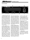
SVP-1500 Bass Amplifier
5
The Rear Panel
STEREO MONO
MODE
10 10 12 121413 13
8 99 9 11
MODEL:
SERIAL:
LINE: V ~ Hz
WATTS: MAX
SVP-1500
SVP15OOU12B
120 60
1500