


Operator Manual – KLR Series Amplifiers Page - 5
All Rights Reserved Rev 0.72110
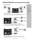
Physical Description
Each model in the KLR-Series is 2RU. The model number is indicated on the left side of the
front panel
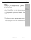
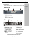
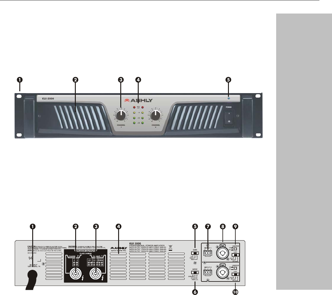
Amplifier Front Panel
1. Mounting Holes – For rack mounting.
2. Air Inflow Vents – Cool air enters here.
3. Channel Attenuators – These knobs adjust
the attenuation of the input signal of each
channel from ∞ to 0.
4. Signal, Clip, and Protect LEDs – Indicates
output level of –30, -20, 0dB, Clip, and amplifier
protect.
5. Power Switch and LED – Switches the unit on
or off.
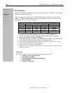
Amplifier Rear Panel
1. AC Cord – For connection to the AC mains
2. CH 2 Output Connector – This connector
provides the amplifier’s Channel 2 output.
3. CH 1, CH 2, Bridged Output Connector –
This connector provides the amplifier’s Channel
1, channel 1 and 2, or bridged output.
4. Air Outflow Vents – Warm air exits here.
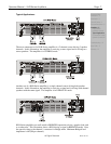
5. Gain Switch – The Gain switch sets both
channel’s gain to 1V, 32dB, or 26dB sensitivity.
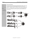
6. Mode Switch – This switch selects the
amplifier’s operating mode (Bridge, Stereo, or
Parallel Mono).
7. 3-Pin Euroblock Input Connectors – These
connectors are used for balanced or
unbalanced input signals.
8. Combination XLR, 1/4” TRS Input
Connectors – These connectors are used for
balanced or unbalanced input signals.
9. Limiter Switch – This switch engages the
limiter. There is a separate limiter for each
channel.
10. HPF Switch – This switch selects the input
HiPass filter to 30Hz, 50Hz, or Off.
WARNING: Do not remove the mains connector ground.
Important Safety
Instructions – 2
Introduction - 3
The KLR Series - 4
Physical Description - 5
Front Panel
Rear Panel
Installation - 6
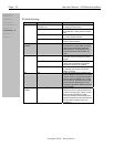
Troubleshooting - 10
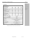
Spec Table - 11
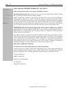
Warranty - 12