


1-4 Chapter1:ProductIntroduction
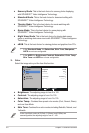
6. Power Indicator
• Thecolordefinitionofthepowerindicatorisasthebelowtable.
Status Description
Blue ON
Amber Standbymode
OFF OFF
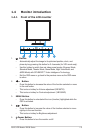
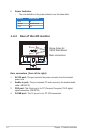
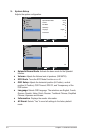
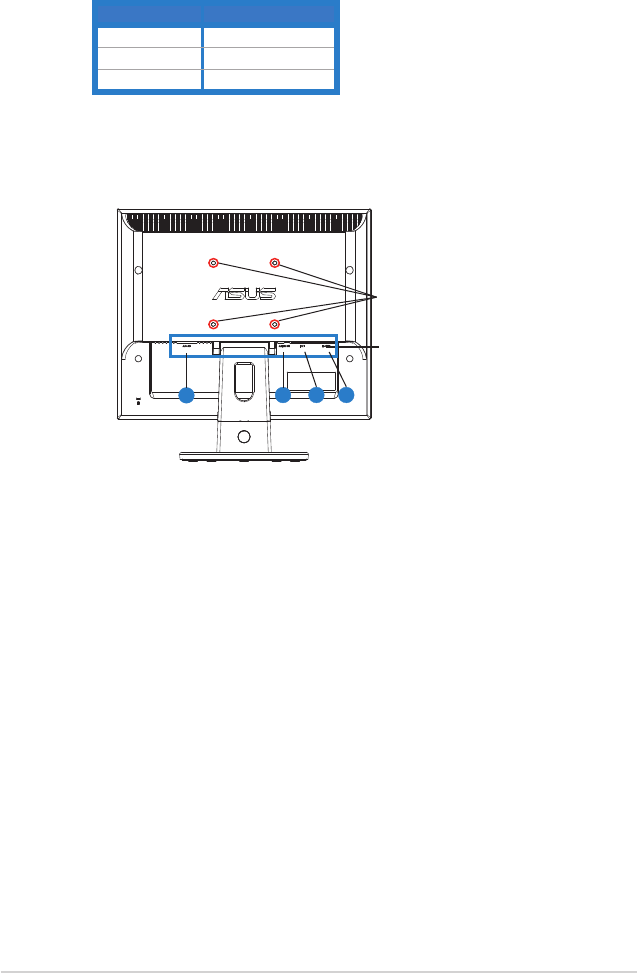
1.4.2 Rear of the LCD monitor
4
3
2
1
Screwholesfor
VESAWallMount
Rear connectors
Rear connectors (from left to right)
1. AC-IN port. Thisportconnectsthepowerconnectorfromthebundled
powercord.
2. Audio-in port.ThisportconnectsPCaudiosourcebythebundledaudio
cable.(VB199T/S)
3. DVI port.This24-pinportisforPC(PersonalComputer)DVI-Ddigital
signalconnection.(VB199T/N)
4. D-SUB port.This15-pinportisforPCVGAconnection.