8
Back panel
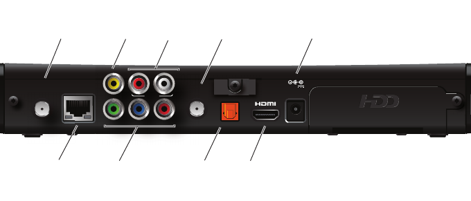
The following illustration shows the ports and connectors on the back of the receiver.
TO WALL (VIDEO IN)
Connects the HPNAv3 in-home network over coaxial cable, if applicable.
NETWORK
Connects the Ethernet network cable, if applicable.
Y Pb Pr
Connects the receiver to a high-definition TV or home theater receiver using a
component video connection.
VIDEO OUT
Connects the receiver to a standard-definition TV using a composite video connection.
AUDIO
Connects the receiver to a TV or home theater receiver using an analog audio
connection.
TO TV
Connects the set-top box to the RF/Antenna connector on your TV or VCR (optional).
OPTICAL
Connects the receiver to a TV or home theater receiver using a digital audio
connection.
HDMI
Connects the receiver to a high-definition TV or home theater receiver using an HDMI
connection.
POWER
Connects the power adapter to the receiver. The LED lights green when the receiver is
receiving power from the wall outlet.
TO WALL
(VIDEO IN)
AUDIO
YPbPr
VIDEO OUT
R
L
NETWORK
TO TV
OPTICAL
POWER
+12V
1.5A MAX.
Coaxial
input
Component
video
output
Analog
audio
output
HDMI
output
Network
port
Composite
video
output
Power
Digital audio
output
(optical)
RF
output


